6 C288M-G (8/05)
2. Install the conduit fittings or glands. Refer to one of the following installation methods:
METHOD 1 – INSTALL A CONDUIT FITTING TO THE BOTTOM OF THE MOUNT
•
Remove the 0.75-inch (1.91 cm) NPT plug.
•
Install a conduit fitting in the 0.75-inch NPT hole.
METHOD 2 – INSTALL THE CONDUIT FITTINGS/GLANDS TO THE BACK OF THE MOUNT
•
Insert the male end of the gland or conduit fitting into the cable hole located on the back plate of the mount.
•
Hold the gland or conduit fitting in the hole with one hand while you reach, with the other hand, into the mount through the
access hole.
•
Attach the fitting nut to the gland or conduit fitting, and rotate the fitting nut to hand-tighten.
•
Repeat the above steps to install a second gland or conduit fitting.
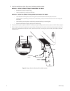
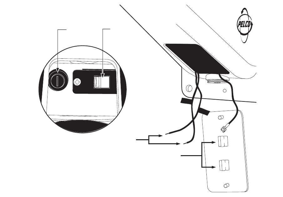
3. The transformer is preset to operate at 120 VAC. If necessary, change the voltage selection switch to operate at 230 VAC. Refer to Figure 2.
4. Refer to Figure 2 and install the proper fuse for the set voltage. The fuse holder is located to the left of the voltage selection switch. The
mount arm is shipped with extra fuses. For 120 VAC, use the 1.6A, 120 VAC, fast-acting fuse; or for 240 VAC, use the 500 mA, 240 VAC,
fast-acting fuse.
Figure 2.
Voltage Selection Switch and Fuse Holder Location
1
15V
TRANSFORMER
POWER
FUSE
HOLDER
VOLTAGE
SELECTION
SWITCH
SPARE FUSE
STORAGE
AC
LOW
(
N
E
UT)
AC
HI
(HOT
)


