


PC I
SLOT1 SLOT2 SLOT3
COMPONENT/RGB IN
AUDIO
RL
P
R
/C
R
/R P
B
/C
B
/B
Y/G
HDMI
AV OUT
HDMI
AV OUT
HDMI
AV OUT
HDMI
AV OUT
SLOT3
COMPONENT/RGB IN
AUDIO
RL
P
R
/C
R
/R P
B
/C
B
/B
Y/G
AUDIO
OUT
Y , P
B,P R,
OUT
P
R
P B
Y
L
R
C
O
MP
O
NENT VIDE
O
O
UT
12
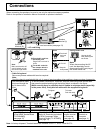
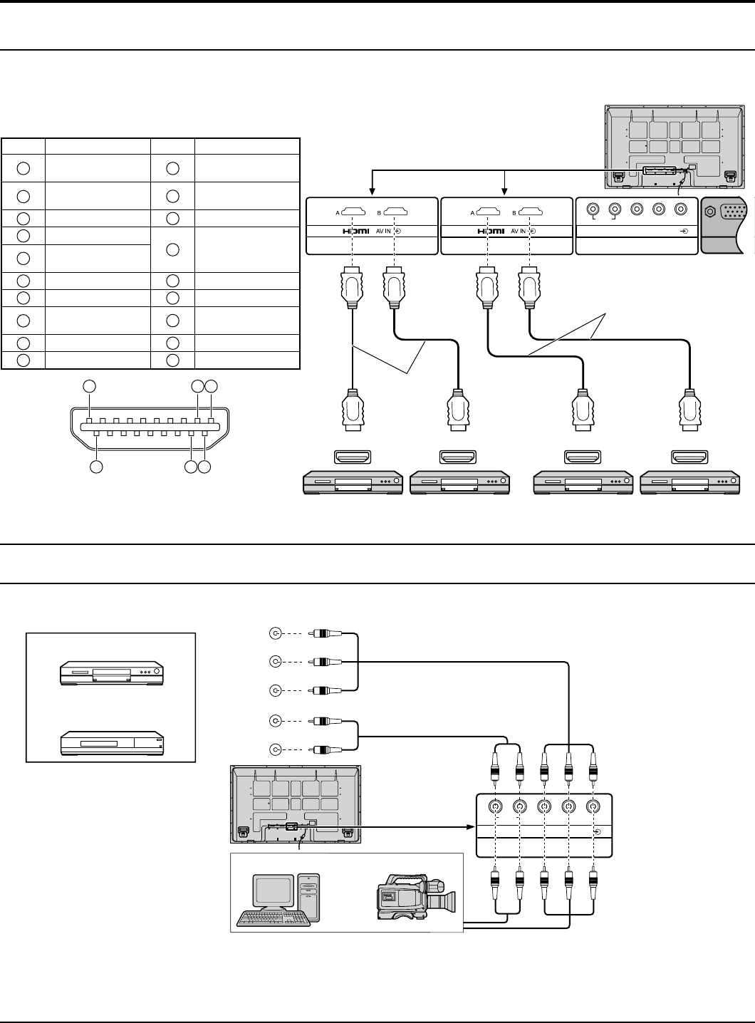
Connections
COMPONENT / RGB connection
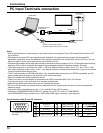
Notes:
Change the “COMPONENT/RGB-IN SELECT” setting in the “SET UP” menu to “COMPONENT”
(when COMPONENT signal connection) or “RGB” (when RGB signal connection). (see page 39)
Additional equipment, cables and adapter plugs shown are not supplied with this set.
SYNC ON G signal is needed. (see page 41)
•
•
•
Computer RGB Camcorder
or
DVD
Example of input signal source
Digital TV-SET-TOP-BOX
(DTV-STB)
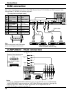
HDMI connection
This unit has terminal boards equivalent to Dual HDMI Terminal Board (TY-FB10HMD) and RCA Component Video
Terminal Board (TY-42TM6Z) as standard equipment.
HDMI cables
DVD Player or SET-TOP-BOX
(HDMI compatible machines only)
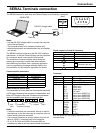
[Pin assignments and signal names]
19
3 1
4
2
18
Note:
Additional equipment and HDMI cables
shown are not supplied with this set.
Pin No.
Signal
Pin No.
Signal
1
T.M.D.S Data2+
11
T.M.D.S Clock
Shield
2
T.M.D.S Data2
Shield
12
T.M.D.S Clock-
3
T.M.D.S Data2-
13
CEC
4
T.M.D.S Data1+
14
Reserved
(N.C. on device)
5
T.M.D.S Data1
Shield
6
T.M.D.S Data1-
15
SCL
7
T.M.D.S Data0+
16
SDA
8
T.M.D.S Data0
Shield
17
DDC/CEC
Ground
9
T.M.D.S Data0-
18
+5V Power
10
T.M.D.S Clock+
19
Hot Plug Detect
HDMI cables