DUAL-THERMOSTAT GAS HEATER
:
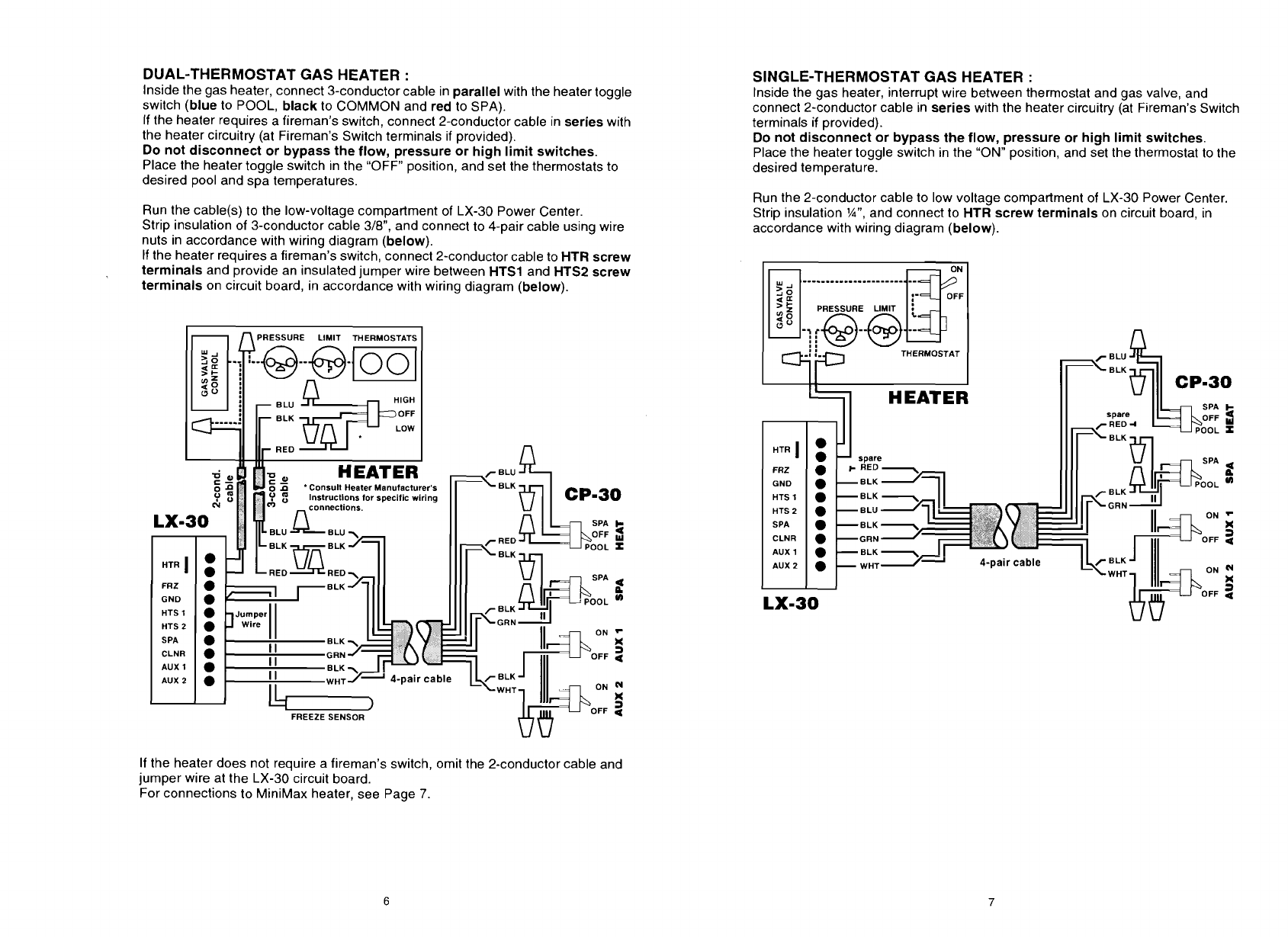
Inside the gas heater, connect 3-conductor cable in parallel with the heater toggle
switch (blue to POOL, black to COMMON and red to SPA).
If the heater requires a fireman's switch, connect 2-conductor cable in series with
the heater circuitry (at Fireman's Switch terminals if provided).
Do not disconnect or bypass the flow, pressure or high limit switches.
Place the heater toggle switch in the "OFF" position, and set the thermostats to
desired pool and spa temperatures.
Run the
cable(s) to the low-voltage compartment of LX-30 Power Center.
Strip insulation of 3-conductor cable
3/8", and connect to 4-pair cable using wire
nuts in accordance with wiring diagram (below).
If the heater requires a fireman's switch, connect 2-conductor cable to
HTR
screw
terminals and provide an insulated jumper wire between
HTS1
and
HTSP
screw
terminals on circuit board, in accordance with wiring diagram (below).
SINGLE-THERMOSTAT GAS HEATER
:
lnside the gas heater, interrupt wire between thermostat and gas valve, and
connect 2-conductor cable in series with the heater circuitry (at Fireman's Switch
terminals if provided).
Do not disconnect or bypass the flow, pressure or high limit switches.
Place the heater toggle switch in the "ON" position, and set the thermostat to the
desired temperature.
Run the 2-conductor cable to low voltage compartment of LX-30 Power Center.
Strip insulation
%I",
and connect to
HTR
screw terminals on circuit board, in
accordance with wiring diagram (below).
PRESSURE LIMIT
I
I
,
m
THERMOSTAT
CP-30
SPA
I-
spare
RED
4
OFF
3
ELK
GND
-ELK
HTS
1
-ELK
HTS
2
-ELU GRN
ON
'
SPA -ELK
)<
CLNR -GUN
a
OFF
4
AUX
1
-ELK
AUX
2
-
WHT
ELK
LX-30
If the heater does not require a fireman's switch, omit the 2-conductor cable and
jumper wire at the LX-30 circuit board.
For connections to
MiniMax heater, see Page
7.


