


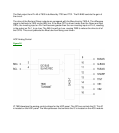

HOP Signal Processing
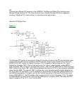
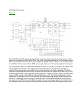
Figure 22
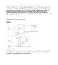
The Y/G, B/Pb, and R/Pr signals are fed to their respective sharpness controls. If the input is a YUV
signal, the Y signal is fed to Pin 28 of 7600. The U and V signals are fed to the Tint Control circuit and
then to Pins 27 and 26 of 7600. If the input is RGB, the signals are fed to Pins 31, 32, and 30 of 7600
to an RGB to YUV converter. When RGB input is used, there is no Tint control available for the signal.
The input selector switch in 7600 selects between the YUV on Pins 28, 27, and 26 or the output of the
internal RGB/YUV converter. The signal is fed to the RGB insertion circuits where the OSD is
inserted. The signal is then fed to a White Point circuit and then to the Output Amplifier. The White
Point and Output Amplifier has the Drive controls and Cutoff controls. Input from the ABL line on Pins
43 makes adjustments in the brightness levels to adjust for changes in beam current. The AKB pulses
from the CRTs are fed to Pin 44 to the Cathode Calibration circuit. The Cathode Calibration circuit
adjusts the cutoff levels of the CRTs to maintain the correct gray scale tracking. When the set is first
turned On, a calibration pulse is output on the RGB lines. The Cathode Calibration circuit monitors
this pulse on the AKB line to set the Black level and the maximum drive voltage for the cathode. Once
the Calibration has taken place, the Output Amplifier switches to the RGB drive signal as the output.