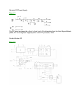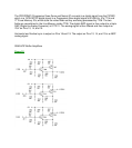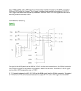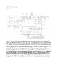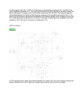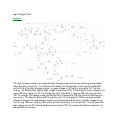
The Blue signal is fed to Pin 1 of 7410. It is also fed to a Low Pass filter consisting of 5411 and 5410. This
path is amplified by transistor 7411. The Low Pass filter blocks the Higher frequencies as well as shifting the
phase of the signal. The output of the Low Pass filter is also fed to Pin 4 of 7410. The mixing of these two-
phase shifted signals only allows the High frequency component to be amplified and output on Pin 12. The
gain of the High frequency component is controlled by the Sharpness voltage, which is applied to Pins 8 and
10. The two signals are combined at Pin 12 of the IC. If the input is a Blue signal it is amplified by 7412 and
buffered by 7413. If the input is a U signal, it is buffered by 7414.
HOP Tint Control
Figure 24
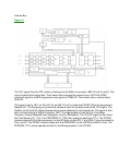
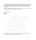
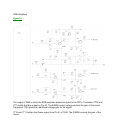
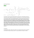
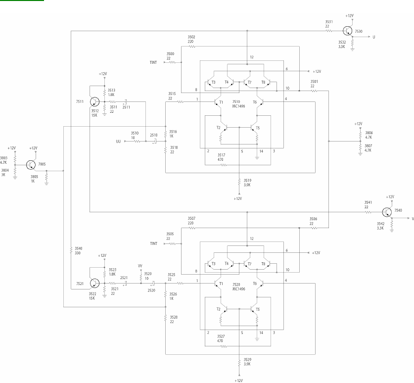
IC 7510 amplifies the U signal while 7520 amplifies the V signal. The Tint control voltage changes the
balance between the U and V signals to change causing the tint of the picture to change.


