


4
CONNECTIONS
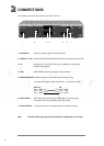
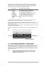
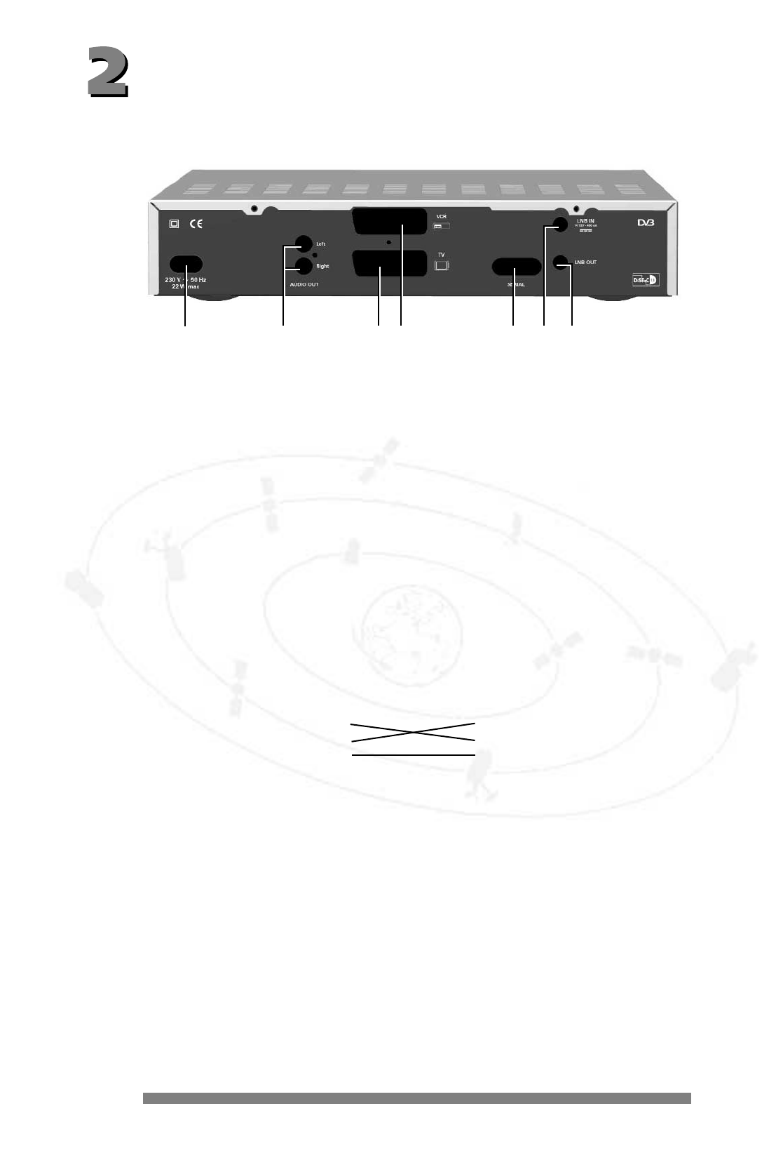
The following connections are located on the back of the unit:
1 - 230 V/50 Hz: Connect the power cable to the power socket.
2 - AUDIO TV L & R: Audio output, left and right-hand channel for connecting to a stereo unit.
3 - TV: Connect the TV connection socket to your television unit using the
SCART cable supplied.
4 - VCR: VCR SCART socket for connecting a video recorder.
5 - DATA INTERFACE: RS 232 interface for serial data transfer during servicing.
0-modem cable (pins 2 and 3 crossed, pins 1, 4, 6-9 are not used).
Receiver: PC:
Pin 2 = RXD Pin 2 = RXD
Pin 3 = TXD Pin 3 = TXD
Pin 5 = GND Pin 5 = GND
6 - SAT-IF INPUT: Sat-IF signal input and output for LNB supply and control signals
connect the cable of your satellite unit to this socket.
7 - SAT-IF OUTPUT: IF signal output (e.g. for feeding through an analogue receiver).
Note: The label showing the type and serial number is underneath your receiver.
1234 567