


English
11
Connections
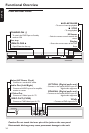
L
R
AUDIO OUT
VIDEO
OUT
S-VIDEO
OUT
Pr
Pb
Y
DIGITAL OUT
COAXIAL OPTICAL
AUDIO
IN
V (Pr/Cr)
U (Pb/Cb)
Y
S-VIDEO
IN
VIDEO IN
COMPONENT
VIDEO IN
AUDIO
IN
V (Pr/Cr)
U (Pb/Cb)
Y
S-VIDEO
IN
VIDEO IN
COMPONENT
VIDEO IN
2
1
IN
IN
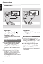
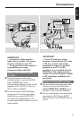
IMPORTANT!
– Component Video provides
higher picture quality. This option
must be available on your TV.
– Progressive Scan video quality is
only possible when using
Component Video (Pr Pb Y).
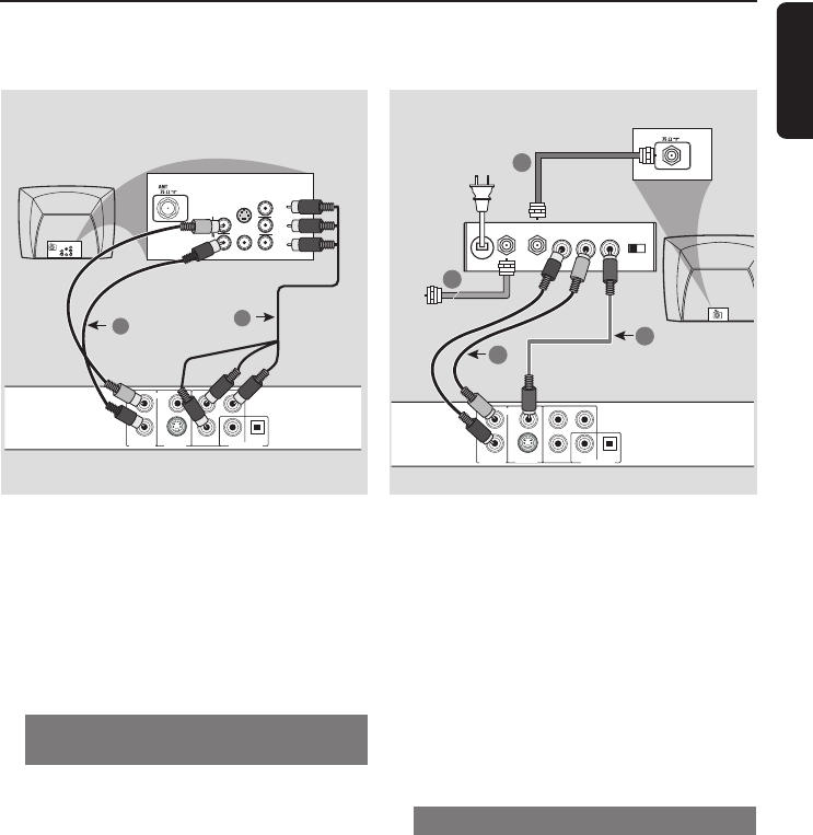
Using Component Video jacks
(Pr Pb Y)
1 Use the component video cables
(red/blue/green) to connect the DVD
Player’s Pr Pb Y jacks to the
corresponding Component video in jacks
(labeled as Pr/Cr Pb/Cb Y or YUV) on
the TV (cable not supplied).
2 To hear the sound of this DVD Player
through your TV, use the audio cables
(white/red) to connect AUDIO OUT
(L/R) jacks of the DVD Player to the
corresponding AUDIO IN jacks on the TV
(cable supplied).
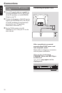
IMPORTANT!
–If your TV only has a single
Antenna In jack (labeled as 75 ohm
or RF In), you will need an RF
modulator in order to view DVD
playback on the TV. The RF
modulator is not supplied with the
DVD Player. See your electronics
retailer or contact Philips for details
on RF modulator availability and
operations.
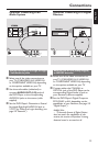
Using an accessory RF modulator
1 Use the supplied composite video cable
(yellow) to connect the DVD Player’s
yellow VIDEO OUT (CVBS) jack to
the video in jack on the RF modulator.
2 Use the supplied audio cable (white/red)
to connect the DVD Player’s AUDIO
OUT (L/R) jacks to the AUDIO jacks on
the TV.
L
R
AUDIO OUT
VIDEO
OUT
S-VIDEO
OUT
PrPb
Y
DIGITAL OUT
COAXIAL OPTICAL
AUDIO IN
R L
VIDEO
IN
TO TVANT IN
CH3 CH4
3
1
2
4
ANT IN
RF coaxial cable to TV
Back of RF Modulator
(example only)
Antenna or
Cable TV signal