


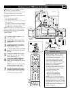
PIP ON/OFF
213
546
879
0
TV
SWAP PIP CH
DN
UP
ACTIVE
CONTROL
FREEZE
SOUND
MUTE
SURF
A/CH
POWER
PICTURE
STATUS/
EXIT
SURF
ITR/
RECORD
HOME
VIDEO
HOME
MOVIES
PERSONAL
SLEEP
REC •
VCR
ACC
MENU/
SELECT
VOL
CH
TV/VCR
FORMAT
SAP
PROG.LISTDOLBY VAV
3
AV2
VIDEO
S-VIDEO
L
Pb
Pr
VIDEO
S-VIDEO
L
AUDIO
L
R
AUDIO
L
R
G/Y
R/Pr
B/Pb
V
H
SYNC
L
R
AUDIO
L
R
AUDIO
HD INPUT-AV 4
HD INPUT-AV 5
INPUT-AV 2 SUBWOOFEROUTPUT
INPUT-AV 1
Y
Rear of TV
AMP SWITCH
CENTER CHANNEL AMP INPUT
ANTENNA IN 75Ω
EXT INT
+
_
DVI
DVD/VCR
AUDIO OUT
DVD/VCR
OUT
IN
COAXIAL
Y
Cr
Cb
OPTICAL
S-VIDEO
OUT
COMPONENT
VIDEO OUT
VIDEO
ANT-IN
ANT-OUT
AUDIO
R
L
R
CH3 CH4
L
DIGITAL AUDIO OUT
PCM / BITSTREAM
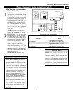
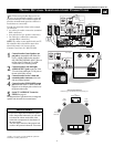
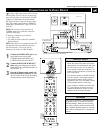
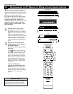
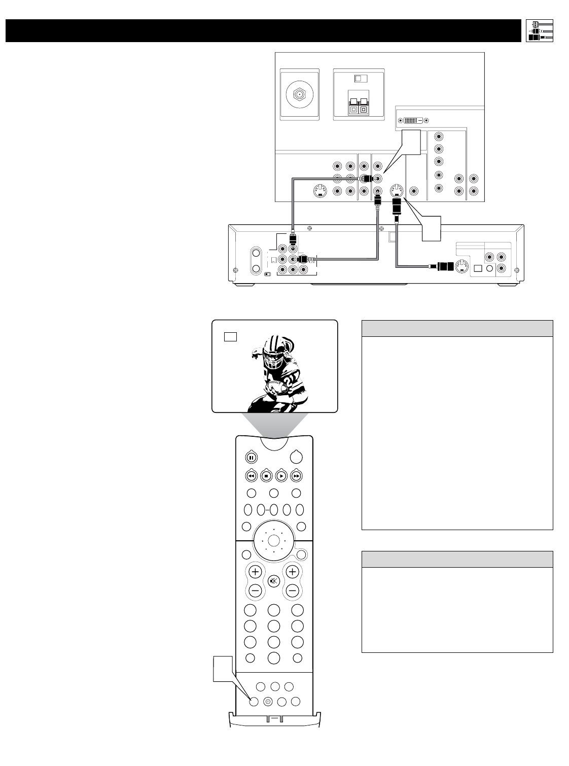
*(Example: Philips DVD/VCR Combi model DV910VHS)
Rear of Device with
S-VIDEO Output*
1
2
T
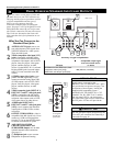
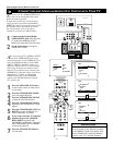
he S(uper)-Video connection on the rear (and
side panel) of the TV can give you better pic-
ture detail and clarity for the playback of S-VHS
VCR tapes or DVDs than the normal antenna
(RF signal) or Video (composite) picture connec-
tions. The example given connects a DVD/VCR
Combi unit to the INPUT-AV 2 jacks on the rear
of the TV.
NOTE: The accessory device must have an
S-VIDEO output jack to make the connection
explained on this page.
To make the connections, you will need:
• one S-Video cable
•two cables for audio connections (standard
RCA connectors).
NOTE: The cables are not supplied with your TV.
You should be able to buy them at most stores
that sell electronics. Or you can call our
Customer Care Center at 1-800-531-0039.
1
Connect the S-VIDEO OUT jack on the
rear of the accessory device with
S-VIDEO output to the INPUT-AV 2
S-VIDEO jack on the rear of the TV.
2
Connect the DVD/VCR AUDIO OUT
jacks on the rear of the accessory device
to the INPUT-AV 2 AUDIO input jacks on
the rear of the TV.
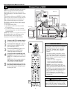
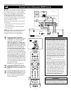
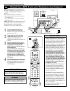
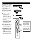
3
Press the AV button on the remote con-
trol as many times as necessary to select
the AV2 source on the TV for the viewing
of materials from your S-Video device.
Connecting Accessory Devices to Your TV
CONNECTING AN S-VIDEO DEVICE
•To simplify making connections, audio
cables are often color coded: red for the
right channel, and white for the left chan-
nel. The jacks on your TV are likewise
color coded to match the connectors. To
make S-Video connections, you must use
an S-Video cable.
•You can also connect a satellite receiver,
laser-disc player, video-game player, or
other accessory device with S-Video
capability to the TV in a manner similar
to the example shown on this page.
• If you connect a satellite receiver to the
TV, you will need to use the receiver’s
channel-memorization system to store
channels in the receiver’s memory.
HELPFUL HINTS
Video sources that show a constant nonmov-
ing pattern on the TV screen can cause pic-
ture-tube damage. When you are not using
your video accessory devices, turn them off.
Also, regularly alternate the use of accessory
video sources with normal TV viewing. See
page 62.
WARNING
13