


47
ANT "A"
75
L
AUDIO
R/MONO
IN-1 IN-2 OUT
VIDEO
S-VIDEO
ANTENNA
OUT
ANTENNA
IN
VIDEO
AUDIO
IN
IN
OUT
OUT
L
R
2
3
4
1
OR
AC-3(ANALOG OFF)
PCM(ANALOG ON)
AUDIO OUT
AUDIO SELECTION
PCM/
AC-3 DIGITAL
1
2
R
L
ANALOG
VIDEO
S
VIDEO OUT
P
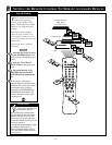
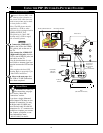
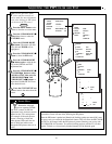
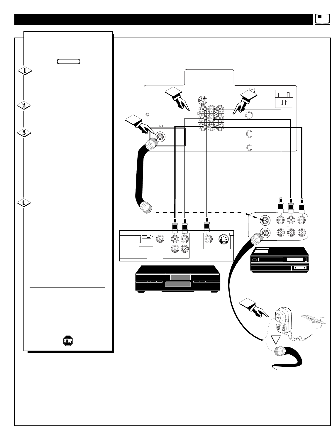
IP hookup is possible with a
VCR and a Digital Video Disc
Player (or similar device).
First connect the original cable
TV signal or Antenna signal to the
ANT IN jack on the back of the
VCR.
Connect the ANT OUT jack on
the rear of the VCR to the ANT”A”
75 Ω input on the rear of the TV.
Connect the yellow Video
Cable from the VIDEO OUT jack
on the VCR to the VIDEO IN jack
on the TV (labeled VIDEO IN-2).
Then, connect the red and white
Audio Cables from the AUDIO OUT
jacks on the VCR to the AUDIO IN
jacks on the rear of the TV (labeled
AUDIO L & R/MONO IN-2).
Connect a second yellow Video
Cable from the VIDEO OUT jack
on the Video Disc Player to the
VIDEO IN jack on the TV (labeled
VIDEO IN-1). Then, connect a sec-
ond set of red and white Audio
Cables from the AUDIO OUT jacks
on the Digital Video Disc Player to
the AUDIO IN jacks on the rear of
the TV (labeled AUDIO L &
R/MONO IN -1).
Note: When selecting the PIP
SOURCE, the Digital Video Disc
Player will appear on the AV 1
channel, and the VCR will appear
on the AV 2 channel.
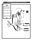
MORE PIP (PICTURE-IN-PICTURE) CONNECTIONS
BEGIN
REAR OF TV
AUDIO
CABLES
(RED AND
WHITE)
VIDEO
CABLE
(YELLOW)
VCR
DVD (OR SIMILAR)
VIDEO
CABLE
(YELLOW)
OUTSIDE UHF/VHF
ANTENNA OR
CABLE TV SIGNAL
75 OHM
COAXIAL
CABLE
AUDIO
CABLES
(RED AND
WHITE)
75 OHM
COAXIAL
CABLE