


DVR-A05/ DVR-105 Operating Instructions
- 7 -
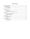
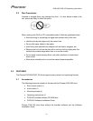
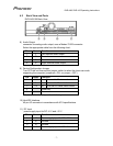
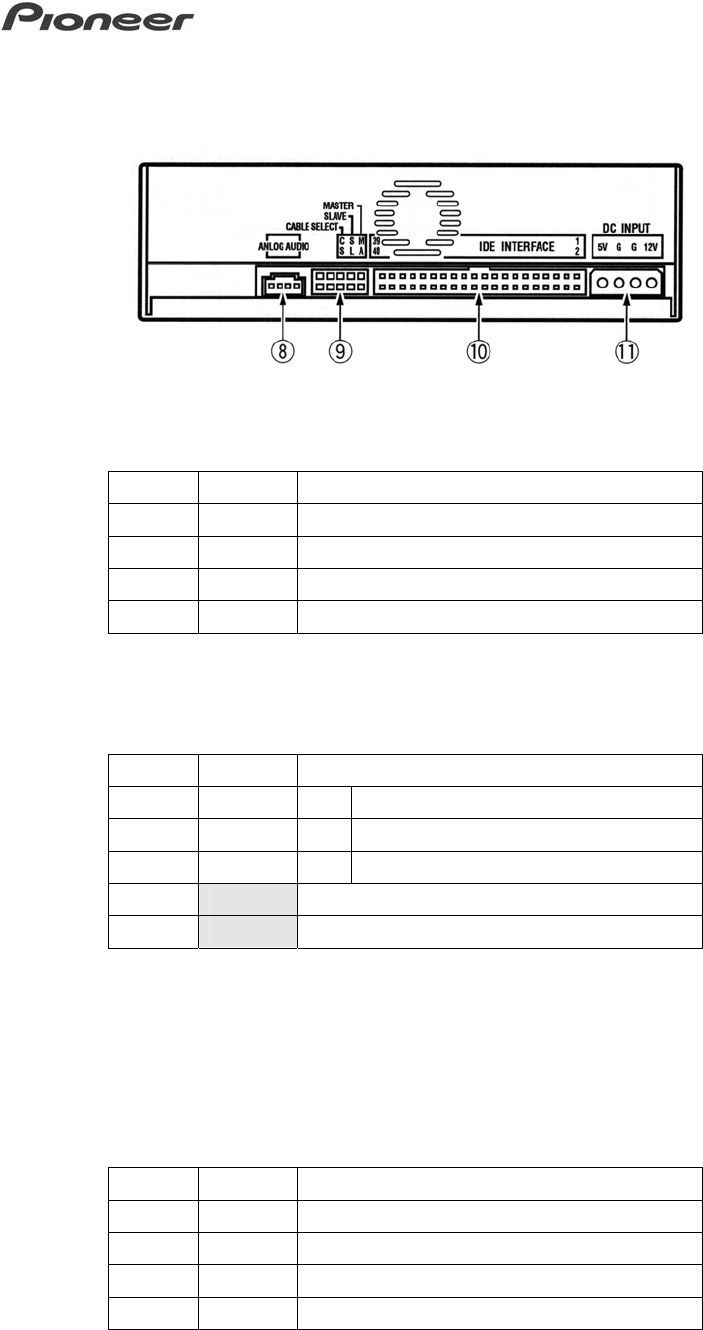
4.2 Back View and Ports
DVR-A05/105 Back View
8) Audio Output
connector for analog audio output, uses a Modex 70553 connector
Select the appropriate cable from the following chart:
Pin Name Function
1 L Left channel audio output
2 G Ground
3 G Ground
4 R Right channel audio output
9) Device Configuration Jumper
Turn OFF the unit then set this jumper switch to select the drive use mode
supporting the computer (jumpered = ON; no jumper = OFF)
Pin Name Function
1 MA* on Drive set to Master mode
2 SL on Drive set to Slave mode
3 CS on Drive set to Cable Select mode
4 Reserved
5 Reserved
* Pin #1 is active when shipped from the factory.
10) Host IDE Interface
40-pin I/O connector in accordance with ATA specifications
11) DC Input
power supply input for DC +5 V and +12 V
Pin Name Function
1 +12 Power supply input for DC +12 V
2 G Ground
3 G Ground
4 +5 Power supply input for DC +5 V