R2XL1 • 16
PROFESSIONAL AUDIO WIRING
You would think it would be easy to connect professional audio equipment
together, but unfortunately it’s not. There can be all sorts of issues that come
up; usually it is AC line hum in your equipment you have to deal with. This is
normally caused by ground loops in the equipment. This effect can be caused
by only a very little current and can wind up having a tremendous impact on
your sound and sanity. We will try to clear some issues up for you by showing
you how to properly wire XLR connectors and what to do in case of hum.
Audio Outputs:
XLR connectors provide a balanced connection that rejects common mode
noise for a cleaner audio signal. Make sure your XLR connectors are WIRED
CORRECTLY! Some manufacturers make them incorrectly so you may want
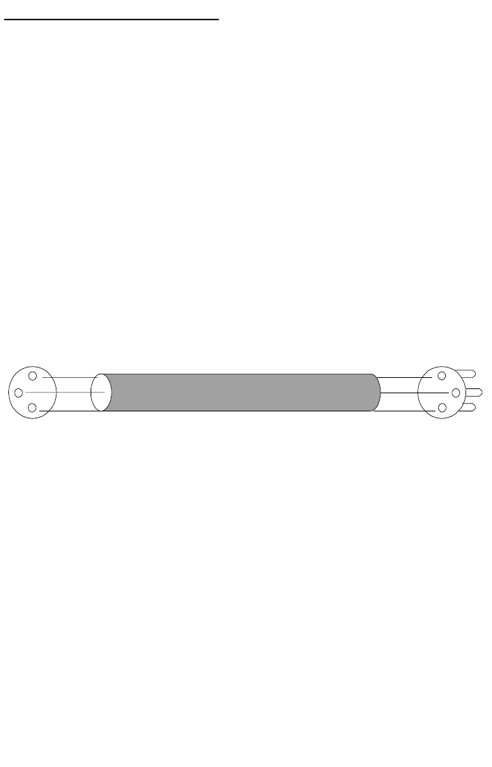
to check the connectors and re-make them to standards if necessary. Current
standards dictate that XLR connectors should be wired as follows:
Ground = pin 1, White = Pin 2, Black = Pin 3. Sometimes you will find red
instead of white. Both ends of the cable are wired in the same order, per the
following diagram.
Across pins 2 & 3 of the XLR inputs look for +4 dBu (1.228VRMS) as
equivalent to 0 dBuV. The audio output can deliver up to a maximum of 21.2V
pk/pk, but then you have to scale the level back down with your audio gain to
get acceptable sound in your destination equipment.
Solving ground loop hum:
We don’t expect you to come across this, but if you do, here is what you may
do.
1. Try running a wire to connect the chassis of your destination equipment
to the source equipment AND the R2XL1. If all are grounded well to-
gether, it may prevent the ground loop from traveling down the audio ca-
bles.
2. Try lifting the shield wire on your XLR cable on the FEMALE end (the
one that plugs into your R2XL1). This will eliminate the path of the
ground loop.
WHITE
BLACK
SHIELD(GND)
2
3
1
WHITE
BLACK
SHIELD(GND)
2
3
1
2 Conductor Shielded Cable
FEMALE MALE


