Installation and Operating Manual 4-20 mA / 2-10 VDC Input Control Module
Start-up
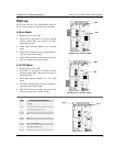
NOTE: The 4-20 mA / 2-10 VDC Module can be set
up for 4-20 mA mode or 2-10 VDC mode, not both.
4-20 mA Mode
1. Restore power to the Y-200.
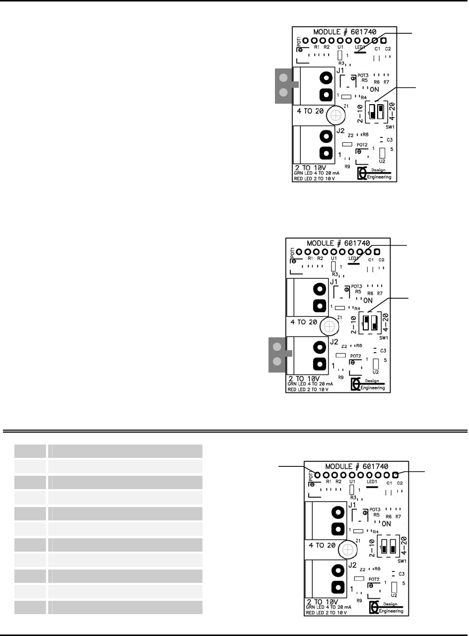
2. Set the SW1-2 dip switch (4-20 mA) to the ON
position, and the SW1-1 dip switch (2-10 VDC)
to the OFF position.
3. Green LED1 indicates Module is in 4-20 mA
mode.
4. Green LED1 flashing once per second indicates a
weak (less than 4 mA) signal.
5. Green LED1 flashing two times per second indi-
cates an overload (over 20 mA) signal.
2-10 VDC Mode
1. Restore power to the Y-200.
2. Set the SW1-1 dip switch (2-10 VDC) to the ON
position, and the SW1-2 dip switch (4-20 mA) to
the OFF position.
3. Red LED1 indicates Module is in 2-10 VDC
mode.
4. Red LED1 flashing once per second indicates a
weak (less than 2 VDC) signal.
5. Red LED1 flashing two times per second indi-
cates an overload (over 10 VDC) signal.
Pin Interface Pin Functions
1 5 VDC
2 4-20 VDC selector switch
3 2-10 mA selector switch
4 4-20 VDC LED drive
5 N/C
6 N/C
7 2-10 mA output
8 4-20 VDC output
9 2-10 mA LED drive
10 GND
LED1
SW1
Module set to 4-20 mA mode
LED1
SW1
Module set to 2-10 VDC mode
Pin 10
Pin 1
3


