


DTA800-B
EN
5
CH4
OUTPUT
TO TV
SMART ANTENNA IN
ANTENNA IN
CH3
TV
ANTENNA
ANTENNA IN
ANTENNA OUT
CH3
CH4
VIDEO
AC~120V
R
AUDIO
L
CH4
OUTPUT
TO TV
SMART ANTENNA IN
ANTENNA IN
CH3
TV
AUDIO IN
L R
VIDEO IN
VIDEO
AC~120V
R
AUDIO
L
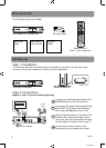
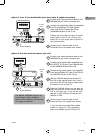
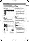
Back of the RCA converter box
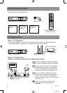
Option 2: Your TV has Audio/Video jacks (red, white & yellow connectors)
From antenna
2
1
3
AC120V
60Hz
Connect your existing antenna cable to the
ANTENNA IN jack of the Converter Box.
Connect the Audio/Video cables (not supplied)
from the Audio/Video OUT jacks (yellow,
white, red) of the Converter Box to the
Audio/Video IN jacks on the TV set.
If there are more than two sets of Audio/
Video jacks on the TV set, connect only
either AV1 or AV2 input jacks to those of
the Converter Box.
Connect the AC power cable of the
Converter Box to a suitable wall outlet.
1
2
3
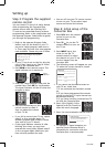
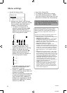
Back of the RCA converter box
VCR
Option 3: You also need to connect your VCR
1
AC120V
60Hz
2
3
4
6
Connect your existing antenna cable to the
ANTENNA IN jack of the Converter Box.
Connect the RF coaxial cable* (supplied) from
the OUTPUT TO TV jack of the Converter Box
to the ANTENNA IN jack of the VCR.
Connect an RF coaxial cable* (not supplied)
from the ANTENNA OUT jack of the VCR to
the ANTENNA IN jack of the TV set.
Slide the CH3/CH4 selector on the back of
the VCR to the channel that is not in use in
your area. The VCR will send its video signal
to Channel 3 or 4 on your TV.
Slide the CH3/CH4 selector on the back of
the Converter Box to the channel that the
VCR is not using; e.g., if you set the VCR
selector to CH3, slide the Converter Box
selector to CH4.
Connect the AC power cable of the
Converter Box to a suitable wall outlet.
* You can also use Audio/Video cables
(similar to option 2) if the connection
jacks are available on the VCR and TV.
1
2
3
4
5
5
6
From antenna
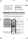
The SMART ANTENNA IN jacks let
you connect a Smart Antenna.
Refer to the antenna’s user manual
for proper connection.
DTA800B_EN(IB).indd 5 17/01/2008