


4
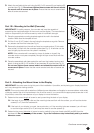
3. Attach the mount arms to the back of your display using the screws identifi ed in steps 1 and 2 (see Fig. 7):
A. If you are using the M6 screws you will also need to use the M6 washers (H). M8 screws do not require
washers.
B. If you are using the longer screws on a display with a curved or recessed back, you may also need to use
the spacers (I). Use one spacer or two spacers stacked as needed. Only use the spacers if necessary.
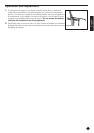
NOTE: Make sure the mount arms are attached with the tilt mechanisms facing outward, exactly as shown in
the illustration (see Fig. 8). Otherwise, the tilt function cannot be accessed.
Part 3 – Final Assembly
1.
Check to make sure the tilt mechanism is fully tightened. It can be tightened using the long Allen key (J)
provided in the hardware kit.
2. With the help of another person, carefully lift your display and place it on the mount. Do not release the
display until the mount arms have securely hooked onto the mount.
3. Make sure the safety locks have successfully engaged by gently pushing up on the display. You should not be
able to remove the display from the mount.
4. If the plastic tabs hang below the bottom of your display they can be trimmed
with a knife or looped back and tucked into the rubber ring located on each tab.
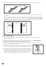
5. If you need to remove the display from the mount, pull the plastic tabs located
at the bottom of the mount arms down and then forward (away from the wall) to
engage the tooth and disengage the safety locks (see Fig. 9). With the help of
another person, carefully lift the display from the mount. Return the tabs to their
original position by pulling them down and pushing them backwards.
Fig.7
For displays with fl at
backs.
For displays with
curved or recessed
backs.
Fig.8
Tilt Adjustment
Mechanism
Tilt Adjustment
Mechanism
1
2
Fig.9