English
3
Attaching the Arms to the TV
IMPORTANT! Use extra care during this part of the installation. If possible, avoid placing your display facedown
as it may damage the viewing surface.
NOTE: This mount comes with a selection of different screw diameters and lengths to accommodate a wide
variety of display models. Not all of the hardware in the kit will be used.
Fig.5
Fig.6
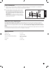
1. Determine the correct length of screw to use by
examining the back of your display:
A. If the back of your display is fl at and the
mounting holes are fl ush with the surface, you
will use the shorter screws (D or F) from the
hardware kit.
B. If the back of your display is curved, has
a protrusion, or if the mounting holes are
recessed, you will need to use the longer screws
(E or G) and spacers (I).
2. Determine the correct diameter of screw to use by
carefully trying one of each size (M6 and M8) from
the hardware kit. Do not force any of the screws
– if you feel resistance stop immediately and
try a smaller diameter screw.
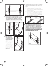
3. Find the tilt adjustment rod and remove one the tilt
adjustment knobs using a screwdriver (see Fig.5).
Place the knob and screw in a safe location.
4. Pass the tilt adjustment rod through both arms
as shown in Fig.6. Make sure the long part of the
tilt adjustment knob faces downwards, exactly as
shown. Replace the missing tilt adjustment knob
using a screwdriver. The fi nal assembly should
match Fig.7.
Concrete/Brick Installation
IMPORTANT! For safety reasons, the concrete wall must be capable of supporting the combined weight of
the mount and the display. The manufacturer takes no responsibility for failure caused by walls of insuffi cient
strength.
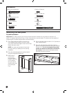
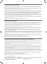
1. Place the wall plate against the wall in the desired
location and level it using the integrated bubble
level.
Fig.3
Fig.4
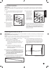
4. Insert a Concrete
Anchor (C) into
each hole so that
it is fl ush with the
concrete surface
(see Fig. 4). A
hammer can be
used to lightly tap
the anchors into
place if necessary.
Continues on next page...
2. While another
person holds the
wall plate in place,
mark six evenly
spaced locations on
the wall for securing
the mount (see Fig.
3).
3. Set the wall plate
aside and drill a 10
mm (3/8”) hole at
each marked location. Remove any excess dust
from the holes.
5. Place the wall plate back against the wall and
attach it using the lag bolts (A) and lag bolt washers
(B) (see Fig. 2). Do not over-tighten these bolts and
do not release the wall plate until all bolts are in
place. Ensure that the wall plate remains level after
all bolts are secured.