17
English
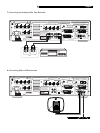
VCR or Digital Video Recorder
See Figure 6
This section describes the hook-up of hi-fi VCRs
with audio and video outputs. VCRs connected
with RF antenna cables are connected directly
to the TV, not to the RSDX-02e.
Output connections:
Connect the output of the VCR to the VCR con-
nector
on the RSDX-02e with a SCART
cable. This cable can carry composite, S-Video,
or RGB video signals as well as left/right ste-
reo analog audio signals.
Input connections:
To record composite video signals from the
RSDX-02e on your VCR, no additional
connnections are required. However, to record
Y-C (S-Video) or RGB video signals from an
STB receiver, you must connect a second SCART
cable from the output of the STB receiver di-
rectly to the input of the VCR.
Digital Audio connection
(for digital video recorders):
If your video recorder has a digital audio output,
you should connect it to the RSDX-02e for play-
back of Dolby Digital recordings.
1. If the video recorder has a coax digital out-
put, connect it to the DIGITAL 1 (STB) in-
put
on the RSDX-02e using a coax digital
cable. The RSDX-02e will need to be
reconfigured to associate this input with the
VCR input. See the
Setup
section of this
manual.
2. If the video recorder has an optical digi-
tal output, connect it to the DIGITAL 2 (TV)
input
on the RSDX-02e using an opti-
cal digital cable. The RSDX-02e will need
to be reconfigured to associate this input
with the VCR input. See the Setup section
of this manual.
3. Connect the DIGITAL OUT connector
on the RSDX-02e to the digital input on the
video recorder with an optical digital cable.
CD Player/CDR Recorder
See Figure 5
Audio Connections:
1. Connect the left and right analog audio
outputs from a CD/CDR to the LEFT/RIGHT
AUDIO TAPE/CDR IN jacks
on the
RSDX-02e with a standard RCA stereo au-
dio cable.
2. With a CDR recorder, connect the LEFT/
RIGHT AUDIO TAPE/CDR OUT jacks
to the audio inputs on the CDR.
Digital Audio connections:
If your CD/CDR has digital audio connections,
you should connect them to the RSDX-02e.
1. If the CD/CDR has a coax digital output,
connect it to the DIGITAL 1 (STB) input
on the RSDX-02e using a coax digital cable.
The RSDX-02e will need to be reconfigured
to associate this input with the TAPE/CDR
input. See the
Setup
section of this manual.
2. If the CD/CDR has an optical digital out-
put, connect it to the DIGITAL 2 (TV) input
on the RSDX-02e using an optical digital
cable. The RSDX-02e will need to be
reconfigured to associate this input with the
TAPE/CDR input. See the
Setup
section of
this manual.
3. When using a CDR recorder, connect the
DIGITAL OUT connector
on the
RSDX-02e to the digital input on the CDR
with an optical digital cable.
NOTE
: No video connections are required for
an CD player/CDR recorder.
Audio Tape Recorder
See Figure 7
Audio Connections:
1. Connect the left and right analog audio
outputs from the audio recorder to the LEFT/
RIGHT AUDIO TAPE/CDR IN jacks
on
the RSDX-02e with a standard RCA stereo
audio cable.
2. Connect the LEFT/RIGHT AUDIO TAPE/
CDR OUT jacks
to the audio inputs on
the tape recorder.
NOTE
: No video or digital connections are
required for an audio tape recorder.
AM Antenna
See Figure 8
The RSDX-02e includes a plastic loop antenna
to receive AM radio signals. Remove this
antenna from the box and locate it near the
RSDX-02e. It can be tacked to a wall, using
the mounting tab provided. Alternatively, you
can fold the center portion of the antenna to
form a tabletop stand.
Connect the 300 ohm twin-conductor wire from
the loop antenna to the push terminals labeled
AM LOOP, attaching one wire to each termi-
nal. It does not matter which wire attaches to
which terminal, but make sure that the con-
nections are solid and that the two wires do
not touch.
You may need to rotate or otherwise reorient
the antenna to find the best position.
NOTE
: To use an outdoor antenna, connect its
300 ohm twin-conductor wire to the termi-
nals in place of the loop antenna.
FM Antenna
See Figure 9
The RSDX-02e is supplied with a T-shaped in-
door FM antenna. Connect the coax F-type plug
to the FM antenna connector on the RSDX-02e.
For best reception, unfold the T-shaped antenna.
Eyelets at both ends of the T allow tacking the
antenna to a wall, if desired. Experiment with
positioning for best reception.
NOTE
: To use an outdoor antenna, connect its
75 ohm coax lead wire to the FM connector
instead of the indoor wire antenna, only af-
ter a professional contractor has installed the
antenna system in accordance with local elec-
trical codes.
AC Input
Your RSDX-02e is configured at the factory for
the proper AC line voltage in the country where
you purchased it (USA: 115 volts/60Hz AC
or CE: 230 volts /50 Hz AC ). The AC line
configuration is noted on a decal on the back
of your unit.
Plug the supplied cord into the AC INPUT
receptacle on the back of the unit. Then, plug
the power cord into an AC wall outlet.
NOTE
: Memorized settings and video labels
are preserved indefinitely, even if the
RSDX-02e is disconnected from AC power.


