


Installation
40 Q-1500d Series Installation/Operation Manual
PRE
L
IMINAR
Y
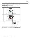
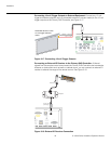
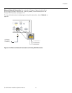
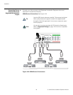
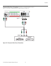
Connecting the Primary
and Secondary DHD
Controllers to Each Other
and to the Brightness
Acceleration Engine
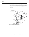
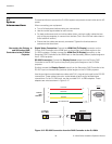
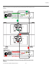
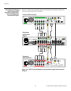
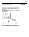
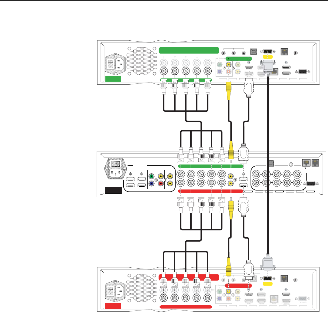
Figure 3-14 shows the connections between the Brightness Acceleration Engine and
Primary and Secondary DHD Controllers.
Figure 3-14. DHD Controller/Brightness Acceleration Engine Interconnection
Diagram
➤
HD1
HD2
Y
G
Pb
B
Pr
R
HV
Y
G
Pb
B
Pr
R
HV
INPUTS
INPUTS
RS-232
ABCDEFG
3Dimension
Processor
Component/SCART
Video 1 Video2
Video 3
Y
PrPb
HDMI 1 HDMI 3
HDMI 2 HDMI 4
ABCDEFG
USB
IR
ABCDE
H
DHD4
Secondary
Pr
R
Y
G
Pb
B
Pr
R
HV
HD2
T
Video 1 Video 2
Video 3PrPb
HDMI 1
HDMI 3
FG
HDMI Out
To Display
RS232
TRIGGERS
RS-232
12
Display Control
IR
Do not connect video sources or control systems to this box.
T
RIGGERS
12
RS2
3
2
R
Vi
de
o3
ABCDE
H
DHD4
Primary
Do not connect any video source directly to this box.
Y
G
Pb
B
Pr
R
HV
HD2
T
Video
Video 3PrPb
HDMI 1
HDMI 3
FG
HDMI Out
Audio Only
HDMI Out
To Display
Ethernet
PC / Control
RS232
TRIGGERS
USB RS-232
123
Display Control
IR
Pr
Pb
P
r
R
Pr
P
b
Vide
o
3
Brightness
Acceleration
Engine
Green
H-Sync
V-Sync
Red
Blue
Green
H-Sync
V-Sync
Red
Blue
Green
H-Sync
V-Sync
Red
Blue
Green
H-Sync
V-Sync
Red
Blue
Primary DHD Controller
Secondary
DHD Controller
Brightness
Acceleration
Engine