4
INTRODUCTION
Product Overview
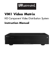
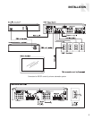
The VM1 Video Matrix works with a multiroom audio
system to distribute analog component video over a
single CAT-5e cable to each zone. Capable of han-
dling high-definition component video signals, it also
provides conversion of composite and S-video signals
in some configurations.
Designed for use with Russound RNET
®
multiroom
solutions, the VM1 provides seamless integration with
the Russound CAA, CAM, and CAV systems.
The VM1 also works with other systems through seri-
al control and offers three control options:
• RNET via RJ-45 modular ports
• RS-232 via DB9 port
• PC control via USB port
The Video Matrix is not IR controllable.
The VM1 has a rack-mountable 2U chassis and
includes the following:
• 24 VDC power supply
• Rear-panel power switch
• Front-panel multifunction LED power and control
data traffic indicators
• Removable rack ears
A red LED on the front panel indicates the power
state of the VM1. It glows steadily to indicate power
on and blinks to indicate an error in powering up.
A green LED blinks to indicate control data traffic on
the serial bus.
VM1 Configurations
The Video Matrix is available in five configurations:
VM1 4 – Provides basic 4x4 switching from analog
component video sources only.
VM1 4UC – Provides 4x4 component video switching
with one upconverter.
VM1 8 – Provides basic 8x8 switching from analog
component video sources only.
VM1 8UC – Provides 8x8 component video switching
with one upconverter.
VM1 8UC2 – Provides 8x8 component video switch-
ing with two upconverters.
The 4x4 configurations provide four source inputs and
four zone outputs. The 8x8 configurations provide
eight source inputs and eight zone outputs.
Each source input has red, green, and blue RCA con-
nectors for component video signals. Each zone out-
put has an RJ-45 8-pole modular connector for a CAT-
5e cable, which feeds an in-wall VMR1 receiver at the
zone’s display location.
The upconverter (UC and UC2) configurations convert
S-video and composite video signals to component
video for distribution while maintaining the original
source resolution. The benefit is that the user doesn’t
have to select a composite or S-video input on the
display to view the sources.
The UC configurations of the Video Matrix provide
conversion for sources 1 and 4. The UC2 configura-
tion provides conversion for sources 1, 4, 5, and 8.
All upconverter configurations provide mini-DIN con-
nectors for S-video signals and RCA connectors for
composite video signals. Internal switches allow the
installer to select which inputs are used, whether
composite, S-video, or component.
VMR1 Receiver
The VMR1 Receiver is a single-gang in-wall device
that installs in each room where component video
distribution is desired. It receives the video signal
from the VM1 through a single CAT-5e cable and pro-
vides red, green, and blue RCA jacks for direct con-
nection to the display with an RGB video cable.
Video Resolution
The Video Matrix system is capable of high-definition
resolution up to 1080p. However, the signal resolu-
tion of the HD sources must be compatible with the
connected displays. Thus, if any display connected to
the Video Matrix is limited to 480p, that output reso-
lution must be selected on each connected source,
unless the display has the ability to scale the image
down from a higher resolution. Otherwise the image
will not display properly.


