


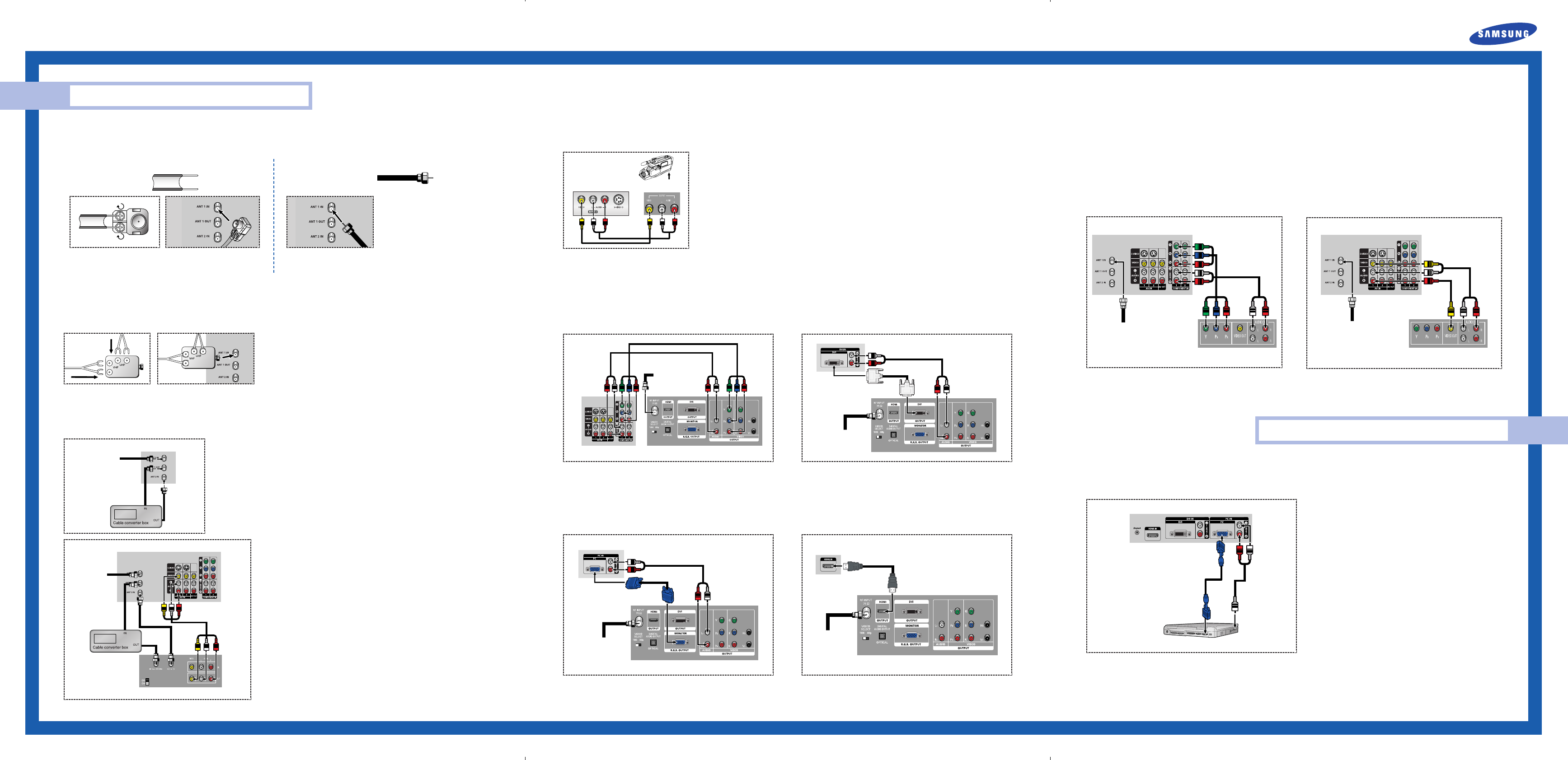
Separate VHF and UHF Antennas
If you have two separate antennas for your TV (one VHF and one UHF), you must combine the two antenna signals before connecting the antennas to the
TV. This procedure requires an optional combiner-adaptor (available at most electronics shops).
Connect both antenna leads to the combiner.
Plug the combiner into the “ANT 1 IN” terminal on the rear panel.
Connecting VHF and UHF Antennas
If you do not have a cable system, you will need to connect an antenna to your TV.
Antennas with 300-ohm Flat Twin Leads
If your antenna looks like this: it has 300-ohm flat
twin leads.
Place the wires from the twin leads under the screws on the 300-75 ohm
adaptor (not supplied). Use a screwdriver to tighten the screws.
Plug the adapter into the “ANT 1 IN” terminal on the rear panel.
Quick Guide
Connections
Connecting Cable TV and VCR
You can connect different cable systems to your TV, including cable without a cable box, and cable with a cable box that descrambles some or all channels.
Connecting a Cable Converter Box
This connection allows you to watch cable and premium channels. You should keep your TV selected
to “ANT 1 IN” so that you can use the TV features. When viewing premium channels, select “ANT 2
IN” and tune the TV to channel 3 or 4 (whichever channel is vacant in your area), then use the
converter box to change channels. You will need two coaxial cables.
NOTES
• When you use a converter box with your TV, there may be features that you can not program
using the remote control, such as programming your favorite channels and blocking channels.
• The output from “ANT 1 OUT” is available when select “Ant.2” in the “Antenna“ channel
menu.
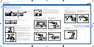
Connecting a Camcorder
The side panel jacks on your TV make it easy to connect a camcorder to your TV. You can use your camcorder to view tapes without using a VCR.
From Cable
TV Rear Panel
Connecting a Cable Converter Box and a VCR
This connection allows you to watch and record basic and premium cable channels,
as well as watch videotapes. You should keep your TV selected to “ANT 1 IN” so
that you can use the TV’s features. When viewing premium channels or recording
with the VCR, select “ANT 2 IN” (whichever channel is vacant in your area), then
use the converter box to change channels.
Caution: If you want to record one channel while watching another channel, a split-
ter (not included) must be added between the cable and “ANT 1 IN”. One output of
the splitter goes to “ANT 1 OUT” and the second output is connected to IN on the
cable converter box.
If you have a mono VCR, connect L/Mono to VCR Audio OUT using only one audio
cable.
If you have a S-VHS VCR, use the S-video connections and remove the video cable.
Do not connect the video cable and the S-video cable to video1 simultaneously.
When you use a converter box with your TV there may be features that you can not
program using the remote control, such as programming your favorite channels and
blocking channels.
Locate the A/V output jacks on the camcorder. They are usually found on the side or back of the camcorder.
Connect a set of audio cables between the AUDIO IN jacks on the TV and the AUDIO OUT jacks on the
camcorder. If you have mono camcorder, connect L(mono) to camcorder audio out using only one audio
cable.
Connect a video cable between the VIDEO IN (or S-VIDEO IN) jack on the TV and the VIDEO OUT jack on
the camcorder. The audio-video cables shown here are usually included with a Camcorder. (If not, check
your local electronics store.) If your camcorder is stereo, you need to connect a set of two cables.
From
Cable
Camcorder
TV Side Panel
Camcorder
Output Jacks
TV Rear Panel
VCR
Connecting to Y, P
B, PR
Connect a set of audio cables between the COMPONENT (1 or 2) audio
(L, R) in jacks on the TV and the AUDIO OUT jacks on the Set-Top Box.
Connect a set of video cables between the COMPONENT (1 or 2) VIDEO
(Y, P
B, PR) in jacks on the TV and VIDEO (Y/PB/PR or Y/CB/CR) OUT jacks
on the Set-Top Box.
NOTE : For an explanation of Component video, see your Set Top Box
owner's manual.
Connecting to DVI (Digital Visual Interface)
Connect a set of audio cables between the DVI audio (L, R) in jacks on the
TV and the AUDIO OUT jacks on the Set-Top Box.
Connect a video cable between the DVI IN jack on the TV and the DVI
OUT jack on the Set-Top Box.
Connecting a DTV Set-Top Box
Incoming Cable
or Antenna
DTV Set-Top Box
TV Rear Panel
TV Rear Panel
DTV Set-Top Box
Incoming Cable
or Antenna
Connecting to R,G,B
Connect a set of audio cables between the PC audio (L, R) in jacks on the
TV and the AUDIO OUT jacks on the Set-Top Box.
Connect a video cable between the PC IN jack on the TV and the R.G.B
OUT jack on the Set-Top Box.
Connecting to HDMI (High Definition Multimedia Interface)
Connect a HDMI cable between the HDMI IN jack on the TV and the HDMI
OUT jack on the Set-Top Box.
NOTE : Please check if the power of HDMI source is on, in case that you fail
to select HDMI from the “Source List” even after you connected the
cable of HDMI source (DTV Set-Top Box, DVD, etc.) to TV.
Incoming Cable
or Antenna
DTV Set-Top Box
TV Rear Panel
TV Rear Panel
DTV Set-Top Box
Incoming Cable
or Antenna
Antennas with 75-ohm Round Leads
If your antenna looks like this: it is an antenna with
75-ohm round leads.
Plug the antenna lead into the “ANT 1 IN” terminal on the rear panel.
PC Display
Connecting to Y, PB
, PR
Connect a set of audio cables between the COMPONENT (1 or 2)
audio (L, R) in jacks on the TV and the AUDIO OUT jacks on the DVD
player.
To enable Component video viewing, connect a set of video cables
between the COMPONENT (1 or 2) VIDEO (Y, P
B, PR) in jacks on the
TV and VIDEO (Y, P
B, PR (or Y, CB, CR) OUT jacks on the DVD player.
NOTE : For an explanation of Component video, see your DVD
player's owner's manual.
Connecting to audio and video jacks
Connect a set of audio cables between the Audio in (1 or 2) jacks on
the TV and the AUDIO OUT jacks on the DVD player.
Connect a video cable between the VIDEO IN (1 or 2) jack on the TV
and the VIDEO OUT jack on the DVD player.
Connecting a DVD Player
The rear panel jacks on your TV make it easy to connect a DVD player to your TV.
TV Rear Panel
DVD Player
Incoming Cable
or Antenna
TV Rear Panel
DVD Player
Incoming Cable
or Antenna
How to Connect Your PC to the TV
This figure shows the Standard Connector-jack panel. The actual configuration on your TV may be different, depending on the model.
NOTE : The “Anynet” jack is for repairs and software upgrades.
Using Your TV as a Computer (PC) Display
15Pin(D-Sub)
Cable
Audio Cable
PC
TV Rear Panel
BP68-00426A-00_QG_0831 9/3/04 3:11 PM Page 1