


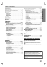
PREPARATION
13
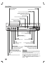
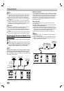
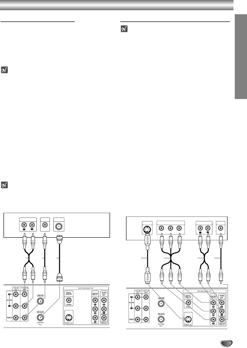
Connections (Continued)
Basic TV Connections
Make one of the following connections, depending on
the capabilities of your existing equipment.
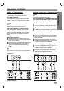
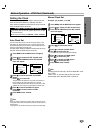
RF coaxial connection
Connect the RF.OUT jack on the DVD+VCR to the
antenna in jack on the TV using the 75-ohm Coaxial
Cable supplied (R).
Note
If you use this connection, tune the TV to the
DVD+VCR’s RF output channel (CH 3 or 4).
How to set the DVD+VCR’s RF output channel
When the DVD+VCR is turned off,
press and hold
CHANNEL (v/V) on the front panel for about five
seconds to change the RF output channel (CH 03 or
CH 04). “RF 03” or “RF 04” appears in the display
window.
Audio/Video connection
11
Connect the DVD/VHS VIDEO OUT jack on the
DVD+VCR to the video in jack on the TV using the
video cable supplied (V).
22
Connect the Left and Right DVD/VHS AUDIO OUT
jacks on the DVD+VCR to the audio left/right in
jacks on the TV (A1) using the supplied audio
cables.
Note
If you use this connection, set the TV’s source selector
to VIDEO.
Optional, Preferred TV Connections
Notes
You can ONLY watch and listen to DVD playback
through the connections shown below.
For using S-VIDEO OUT or COMPONENT VIDEO OUT
jack, set the “TV Output Select” mode on the SETUP
menu to corresponding mode. See page 19.
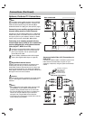
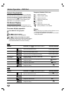
Audio/Video connection
11
Connect the VIDEO OUT jack on the DVD+VCR to
the video in jack on the TV using the video cable
supplied (V).
22
Connect the Left and Right AUDIO OUT jacks of
the DVD+VCR to the audio left/right in jacks on the
TV using the audio cables supplied (A2).
S-Video connection
11
Connect the S-VIDEO OUT jack on the DVD+VCR
to the S-Video in jack on the TV using the optional
S-Video cable (S).
22
Connect the Left and Right AUDIO OUT jacks of
the DVD+VCR to the audio left/right in jacks on the
TV using the supplied audio cables (A2).
Component Video (Color Stream
®
) connection
11
Connect the COMPONENT VIDEO OUT jacks on
the DVD+VCR to the corresponding in jacks on the
TV using an optional Y Pb Pr cable (C).
22
Connect the Left and Right AUDIO OUT jacks of
the DVD+VCR to the audio left/right in jacks on the
TV (A2) using the supplied audio cables.
L
R
AUDIO INPUT
VIDEO
INPUT
ANTENNA
INPUT
Rear of TV
Rear of DVD+VCR
A1 V R
L
R
Y
Pb
Pr
COMPONENT VIDEO INPUT
AUDIO INPUT
L
VIDEO
INPUT
S-VIDEO
INPUT
Rear of TV
Rear of DVD+VCR
S A2 VC