LOCATIONS OF CONTROLS AND INDICATORS
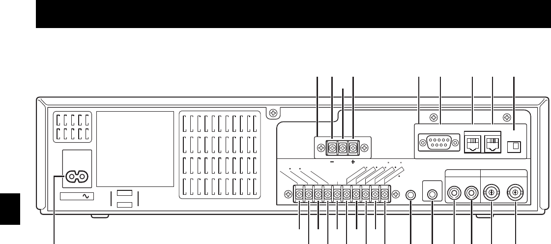
Back Panel (With the RS-485/232C interface board)
1
VIDEO OUT (video output) jack
2
VIDEO IN (video input) jack
3
AUDIO OUT (audio output) jack
4
AUDIO IN (audio input) jack
5
MIC IN (microphone input) jack
6
REMOTE (remote control input) jack
7
SW OUT (switch output) terminal
8
TIMER OUT (timer recording output) terminal
9
TAPE END OUT (tape end output) terminal
F
CONTROL OUT terminal
G
WARNING OUT (warning output) terminal
œ Signals are output when an alarm, clog detection,
video loss, non-recording or mechanism problem
occurs.
H
COM (common) terminal
I
EXT TIMER IN (external timer trigger input) terminal
ALARM REST IN (alarm recording reset input)
terminal
J
SERIES IN (series recording trigger input) terminal
K
CONTROL IN terminal
L
ALARM IN (alarm trigger input) terminal
1 SHOT IN (single image recording trigger input)
terminal
M
AC power input
1
DC power input (SRT-8960P only)
A
DC12-24V IN “–” input terminal
B
Do not use
C
DC12-24V IN “+” input terminal
œ Pay attention to the polarity of the DC12-24V
input terminal (“+”: red screw, “–” : black screw).
2
RS-485/232C interface board (sold separately)
D
RS-232C connector (D-sub 9-pin type)
E
RS-485 A connector (RJ-11)
F
RS-485 B connector (RJ-11)
G
TERMINATE switch
NOTES:
œ The above illustration shows the unit when the
RS-485/232C interface board is installed. If no
RS-485/232C interface board is installed, connectors
and switches D through to G do not appear.
œ The terminal may be damaged by a torque of 0.49
N
.
m (5kg
.
cm) or more and by using screwdriver with a
tip with a diameter of 6 mm or more.
œ Do not connect the RS-485 A and RS-485 B
connectors to a phone line.
œ The 8, F, J and K terminals can be used to select
the input and output signals. (Refer to “SELECTING
INPUT AND OUTPUT TERMINALS” on page 39.)
œ If using the F and K terminals, multiple VCRs can be
operated by operating a single VCR. (Refer to
“SYNCHRONIZATION CONTROL” on page 41.)
AC IN
AUDIO VIDEO
ININ OUTOUT
REMOTE
RS232C
TERMINATE
Do not connect to phone line.
OFF ON
RS485 BA
MIC IN
SW O
U
T
W
A
R
N
ING O
U
T
1
E
XT TIM
E
R
IN
S
ER
I
ES IN
CONTR
O
L IN
ALARM(1 S
H
OT) IN
(
ALAR
M RE
SE
T
)
C
O
N
TROL
O
U
T
TA PE E
ND
O
U
T
TIMER O
U
T
COM
2
D21 E F G
12346 579GIK
8FHJL
SEE MANUAL
DC12-24V IN
M
A
B
C
OPEN COLLECTOR (Max. 1=500mA, 2=50mA)
RQ4QR/EX (SRT-8960P GB) Fri. Sept., 06/2002
English
7


