


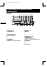
LOCATIONS OF CONTROLS AND INDICATORS
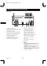
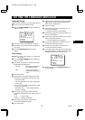
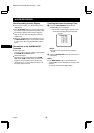
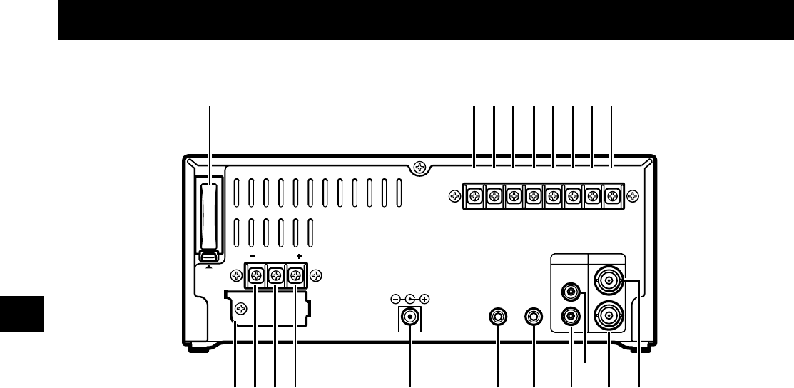
Back Panel
1 Battery compartment cover
2 EXT TIMER IN (external timer input) terminal
3 COM (common) terminal
4 WARNING OUT (warning output) terminal
5 TAPE END OUT (tape end output) terminal
6 SW OUT (switch output) terminal
7 COM (common) terminal
8 ALARM OUT (alarm output) terminal
9 ALARM IN (alarm input) terminal
F VIDEO IN (video input) jack
G VIDEO OUT (video output) jack
H AUDIO IN (audio input) jack
I AUDIO OUT (audio output) jack
J MIC IN (microphone input) jack
K REMOTE (remote control input) jack
L DC 12 V IN (DC 12 V input) jack
M DC 12 V IN “+” input terminal
N Do not use
O DC 12 V IN “–” input terminal
P Fuse cover
NOTES:
•
This terminal board may be damaged by 5 kg-cm or
more torque and using φ6 mm-tip or more size
screwdrivers.
•
Pay attention to the polarity of the DC 12 V input
terminal (“+”: red screw, “–”: black screw).
•
When both the DC 12 V IN jack and the DC 12 V IN
terminals are connected, the input with the highest
voltage will have priority.
AUDIO VIDEO
OUT
OUT
IN
IN
MIC IN
REMOTE
EXT
TIMER IN COM
WARNING
OUT
TAPE
END OUT
SW
OUT COM OUT IN
ALARM
DC12V IN
PUSH
OPEN
1 2 4 6 83 5 7 9
FG
H
IJK
L
MNO
DC12V IN
P
GB
NE4QG/EX (TLS-224P GB) Mon. May, 11/1998
English
5