30 ST11950 and ST12550 Installation Guide, Rev. D
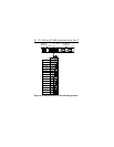
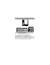
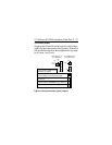
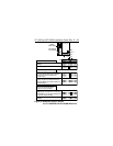
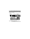
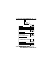
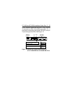
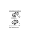
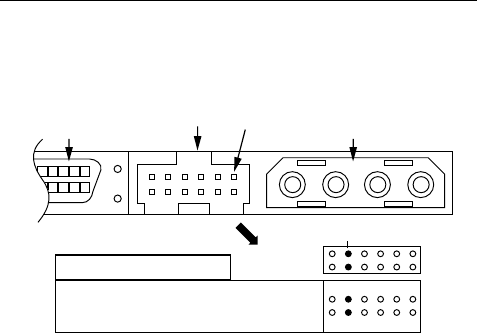
Figures 10a and 10b provide the information necessary
to configure all W and WD drive jumpers not discussed
elsewhere in this manual.
DC Power
Connector
SCSI I/O
Connector
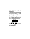
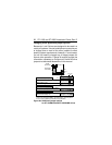
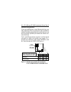
Pin 9 (top pin in this illustration) is
negative (cathode), Pin 10 (bottom pin)
is positive (anode).
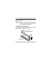
Remote LED Connector*
*Note to subsystem designers: In Europe, a red LED
indicates an error or warning condition. For this reason, you
may want to use a color other than red with this connection.
J5 Pin 1
LED
J5
Figure 10a. Additional jumper options
for ST11950W/WD and ST12550W/WD drives


