


33
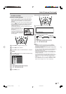
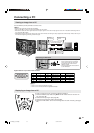
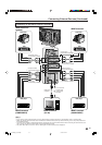
Viewing an Image from a PC
Use the INPUT5 (PC-IN) terminals to connect a PC.
A
• The PC input terminals are DDC1/2B-compatible.
• Refer to page 35 for a list of PC signals compatible with the System.
• Make sure to select the same signal values for the output signal of a PC and the input signal of the LCD TV set before connecting with the
PC. (See pages 34 and 35.)
• Depending on the PC being used, images may not be shown without converting the output signals into external output. Please refer to your
PC’s manuals regarding converting to external output.
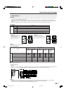
PC
RGB cable (supplied)
To AUDIO
input terminal
To Audio output
terminal
To ANALOG
RGB terminal
To ANALOG RGB
output terminal
ø 3.5 mm stereo minijack cable
(commercially available)
Connecting a PC
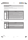
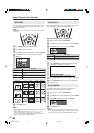
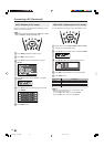
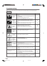
Signal names for 15-pin mini D-sub connecter
15
14
13
12
9
11
10
8
7
6
5
4
3
2
1
Pin No. Signal name Pin No. Signal name Pin No. Signal name
1 R 6 GND (Ground) q Not connected
2 G 7 GND (Ground) w SDA
3 B 8 GND (Ground) e HD
4 Not connected 9
+
5V r VD
5 CSYNC 0 GND (Ground) t SCL
A
• Pin No. 5 is not used for inputting the signal.
• Pin No. 9 is not connected with the supplied RGB cable.
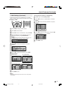
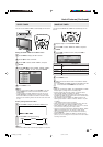
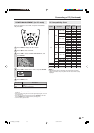
Displaying an Image from a PC
Connecting the RGB cable
Ferrite core
To view an image from a PC, perform the following procedure.
1 Select the INPUT5 (PC) mode using INPUT on the remote control or the LCD TV
set. (See page 16.)
2 Select the PC input signal. (See page 34.)
3 Select the PC sound input mode. (See page 23.)
4 Adjust the “FINE SYNC.” items if the PC image does not come in clearly. (See page
34.)
• Connect the RGB cable making sure
that it fits correctly into the terminal.
Then, firmly secure the connectors
by tightening the screws on both
sides of the plug.
• Do not remove ferrite cores attached
to the RGB cable.
LC-20B8U_E_P33-35.p65 05.2.3, 2:07 PM33