


40
E
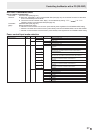
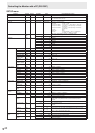
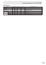
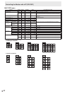
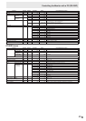
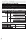
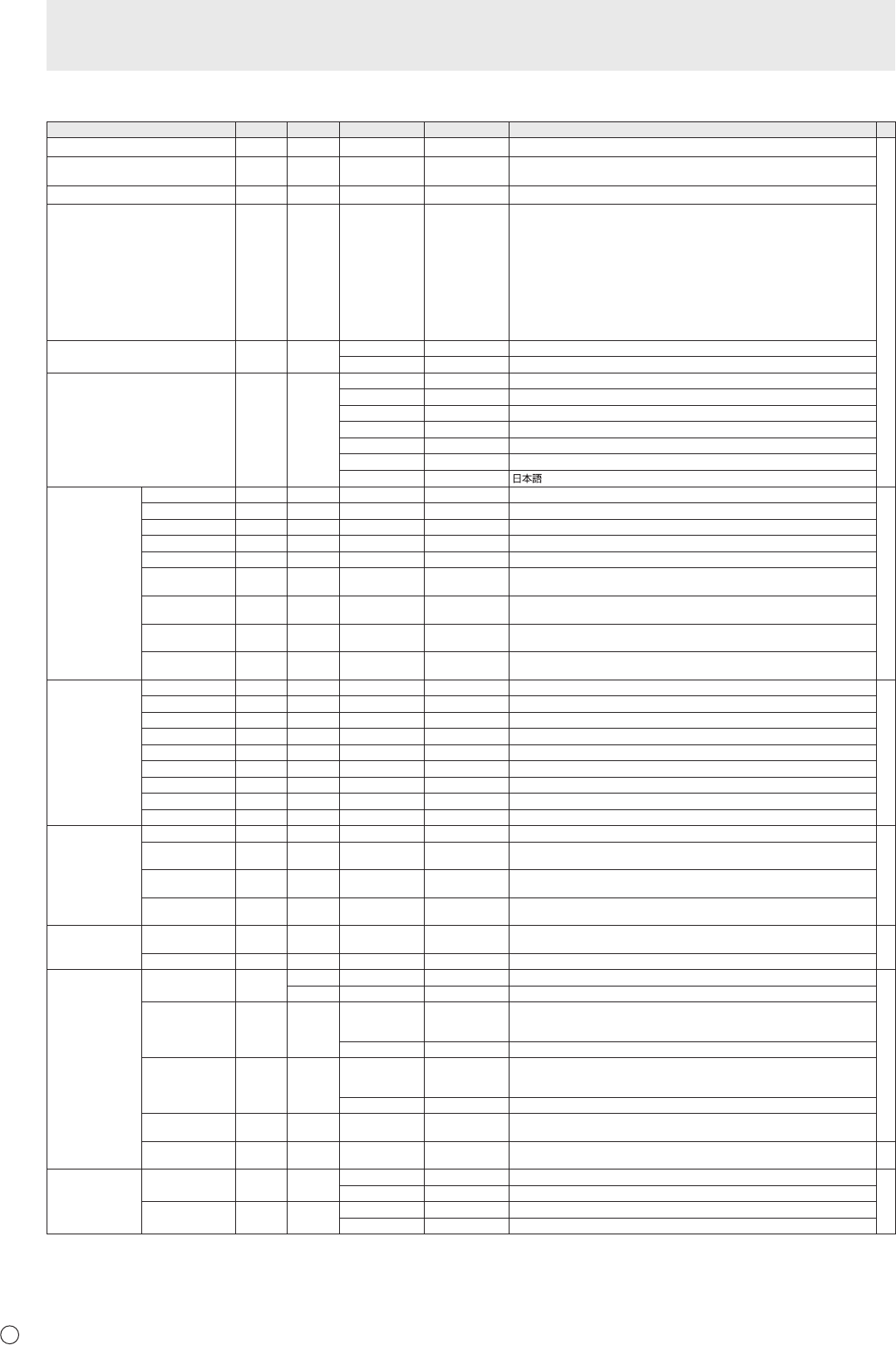
SETUP menu
Function
Command Direction
Parameter Reply Control/Response contents *
DATE/TIME SETTING DATE WR
AABBCCDDEE AABBCCDDEE
AA: Year, BB: Month, CC: Day, DD: Hour, EE: Minute
○
DATE DISPLAY FORMAT DTFT WR
0-2 0-2
0: YYYY/MM/DD, 1: MM/DD/YYYY, 2: DD/MM/YYYY
YYYY: Year, MM: Month, DD: Day
TIME DISPLAY FORMAT TMFT WR
0-1 0-1
0: 24-HOUR TIME, 1: 12-HOUR TIME
SCHEDULE SC01-
SC08
WR ABCDEFFGGH ABCDEFFGGH Schedule of a specied number
A: Schedule 0= Not effective, 1 = Effective
B: Power 0 = OFF, 1 = ON
C: Day of the week 1 0 = Only once, 1 = Every week, 2 = Every day
D: Day of the week 2 0 = Sunday, 1 = Monday through 6 = Saturday,
9 = Not exist
E: Day of the week 3 0 = Sunday, 1 = Monday through 6 = Saturday,
9 = Not exist
F: Hour 00-23
G: Minute 00-59
H: Input 0 = Not specied, 1 = DVI-I, 2 = DisplayPort,
3 = HDMI1, 4 = HDMI2, 5 = D-SUB
“ERR” when LOW POWER is selected for STANDBY MODE.
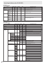
SCHEDULE BRIGHTNESS SB01-
SB08
WR 0-31 0-31 Screen brightness to change
99 99 Disable brightness setting
LANGUAGE LANG WR 14 14 ENGLISH
1 1 DEUTSCH
2 2 FRANÇAIS
3 3 ITALIANO
4 4 ESPAÑOL
5 5 РУССКИЙ
6 6
INPUT SELECT HDMI1 HDSL WR 0-1 0-1 0:PC 1:AV
○
HDMI2 H2SL WR 0-1 0-1 0:PC 1:AV
D-SUB SLDS WR 0-2 0-2 0:RGB 1:COMPONENT 2:VIDEO
HDMI1 AUTO VIEW
HDAW WR 0-1 0-1 0: OFF, 1: ON
HDMI2 AUTO VIEW
H2AW WR 0-1 0-1 0: OFF, 1: ON
HOT PLUG
CONTROL (DVI-I)
HPCT WR 0-1 0-1 0: OFF, 1: ON
HOT PLUG
CONTROL (HDMI1)
HPCH WR 0-1 0-1 0: OFF, 1: ON
HOT PLUG
CONTROL (HDMI2)
HPH2 WR 0-1 0-1 0: OFF, 1: ON
EDID SELECT
(DVI-I)
DVED WR 0-2 0-2 0: AUTO, 1: DIGITAL, 2: ANALOG
AUDIO SELECT DVI-I
ASDP WR 1-2 1-2
1: AUDIO1, 2: AUDIO2
○
D-SUB[RGB]
ASAP WR 1-2 1-2
1: AUDIO1, 2: AUDIO2
HDMI1[PC]
ASHP WR 0-2 0-2
0: HDMI, 1: AUDIO1, 2: AUDIO2
HDMI1[AV]
ASHA WR 0-2 0-2
0: HDMI, 1: AUDIO1, 2: AUDIO2
HDMI2[PC]
AH2P WR 0-2 0-2
0: HDMI, 1: AUDIO1, 2: AUDIO2
HDMI2[AV]
AH2A WR 0-2 0-2
0: HDMI, 1: AUDIO1, 2: AUDIO2
D-SUB[COMPONENT]
ASC2 WR 1-2 1-2
1: AUDIO1, 2: AUDIO2
D-SUB[VIDEO]
ASV2 WR 1-2 1-2
1: AUDIO1, 2: AUDIO2
DisplayPort
ASDI WR 1-3 1-3
1: AUDIO1, 2: AUDIO2, 3: DisplayPort
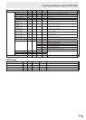
AUDIO OPTION AUDIO OUTPUT
AOUT WR 0-2 0-2
0: VARIABLE1, 1: FIXED, 2: VARIABLE2
○
AUDIO INPUT
LEVEL1
AIVP WR 0-1 0-1
0: 1.0Vrms, 1: 0.5Vrms
AUDIO INPUT
LEVEL2
AIV2 WR 0-1 0-1
0: 1.0Vrms, 1: 0.5Vrms
MONAURAL
AUDIO
MONO WR
0-1 0-1
0: OFF, 1: ON
COMMUNICATION
SETTING
RS-232C/LAN
SELECT
CTLS WR 0-1 0-1 0: RS-232C 1: LAN
○
BAUD RATE
BAUD WR 0-2 0-2 0: 9600bps, 1: 19200bps, 2: 38400bps
ID SETTING ID NO.SETTING IDST W 0-255 Sets the monitor’s ID number. (“0” means “no ID number”.)
○
R 0-255 Returns the monitor’s ID number.
ID NO. SETTING
(ONCE)
IDSL W 1-255 Sets a monitor ID number.
This ID number is only effective for the command immediately after this
command.
0 Clears the ID number if one has been designated.
ID NO. SETTING
(SUBSEQUENT)
IDLK W 1-255 Sets a monitor ID number.
This ID number is effective for the next and all subsequent commands after this
command.
0 Clears the ID number if one has been designated.
ID CHECK IDCK W 0 ID : xxx
IDLK : yyy
Displays monitor’s own ID number and the selected ID number on the screen.
ID DISPLAY IDDP W 0-2 0: OFF, 1: ON, 2: ON (turns OFF after 4 sec.)
(The IP address and MAC address are both displayed.)
-
COPY SETTING
VALUE
SETTING COPY
MODE
CPMD WR 0 0 Copy to all monitors.
○
1-255 1-255 Copy to the monitor with the set ID Number.
SETTING COPY
TARGET
CPTG WR 0 0 Copies the PICTURE menu settings.
1 1 Copies all the settings.
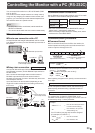
Controlling the Monitor with a PC (RS-232C)