


3
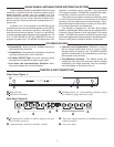
CONNECTING RECEIVERS
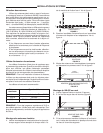
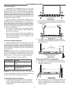
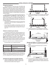
Antenna Distribution
Using low-loss, 50 Ω coaxial cables (RG 58 or equiva-
lent), connect the right and left (Channels 1 through 4, A and
B) RF OUTPUT ports on the WA405 to the corresponding
left and right (A and B) antenna inputs on each receiver.
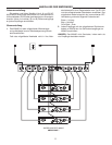
Power Distribution
1. Using the supplied ac power cable, connect the WA405
to an ac power outlet.
If the supplied power cable does not match your mains
outlet, use an IEC 320 type mating connector and the ap-
propriate mains plug. The supplied cord uses Harmonized
IEC Cordage with color coding as follows:
Brown = Line
Blue = Neutral
Green/Yellow = Ground
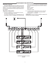
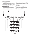
2. Using the supplied dc power cables, connect each re-
ceiver to ONE of the four dc power outputs on the
WA405.
NOTE: Do not overload the WA405 by attempting to power
more than four receivers.
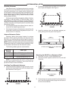
WA405 SETUP
FIGURE 8
12.5 – 18.9 VDC
ANTANT
OUTPUTS
BAL
MIC LINE
POWER
AB
12.5 – 18.9 VDC
ANTANT
OUTPUTS
BAL
MIC LINE
POWER
AB
12.5 – 18.9 VDC
ANTANT
OUTPUTS
BAL
MIC LINE
POWER
AB
12.5 – 18.9 VDC
ANTANT
OUTPUTS
BAL
MIC LINE
POWER
AB