AN.No.G1216B1N000-3D0E
- 7 -
2. CIRCUIT CONFIGURATION
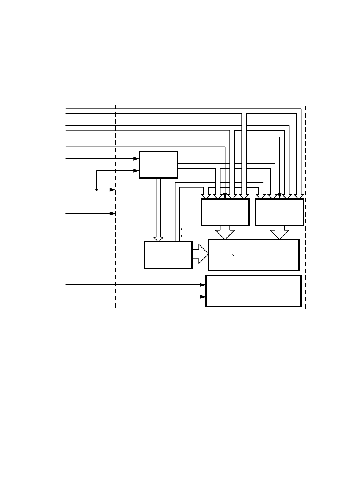
2.1 Block Diagram
This product consists of two HD61202 segment drivers, an HD61203 common driver and a bias
voltage generator. Figure 2 shows the block diagram.
CS2
RST, R/W, D / I, E
DB
0
to DB
7
V
DD
CS1
V
SS
64
128 64 full dot matrix LCD
Segment Driver 1
V
LC
V
a
, V
c
, V
d
, V
f
V
a
V
b
V
e
V
f
Segment Driver 2
Common Driver
Bias Voltage
Generator
FRM
M
CL2
1
2
LED Backlight
LEDA
LEDC
64
64
2.2 Segment Drivers (HD61202)
The segment driver is a 64 drive output CMOS IC. The G1216 is driven with the panel divided into
two right and left displays. A segment driver controls the divided screen. 8 bits of data transmitted
from the MPU are saved in the internal display RAM, and the segment signal is generated to drive the
LC. 1 bit of display RAM data corresponds to 1 dot lighting or non-lighting on the LC panel.
Fi
g
ure 2 Block Dia
g
ram


