


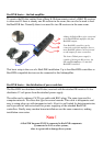


BeeLINK basics – the link amplifier.
To receive the IR data emitted from a Bang & Olufsen remote control, a B&O IR-receiver
is often used. If there is already one IR-receiver in the room, this can also be used to feed
the BeeLINK bus. Normally there is no need for two IR receivers in the same room.
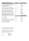
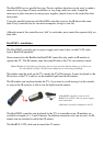
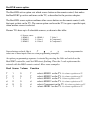
A Bang & Olufsen IR-receiver connected
to the BeeLINK link amplifier with four
BeeLINK outputs.
Four BeeLINK controllers can be
connected to this link amplifier. One or
more BeeLINK splitters can be inserted
to add outputs for more controllers.
The shown 700mA power supply is
capable of driving the IR-receiver, the
link amplifier and up to 15 attached
BeeLINK controllers.
This basic setup is the core of a BeeLINK installation. Up to four BeeLINK controllers or
BeeLINK compatible devices can be connected to this linkamplifier.
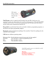
BeeLINK basics – the distribution of power and data.
The BeeLINK bus distributes the IR-data, received with the attached IR-receiver. It also
distributes 12 volt power from the attached power supply.
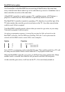
The cable used is ordinary CAT5 type cable with RJ45 plugs. The same type used for
computer network. We chose this type for several reasons. This cable is inexpensive and
easy to crimp plugs on, with inexpensive tools. Also it is well suited for data transmission,
and it provides us with extra leads for power supplying of the attached BeeLINK
controllers. Finally many modern house installations use the same connectors, making
installation even easier.
Note !
A BeeLINK bus must ONLY be connected to BeeLINK components.
If connected to LAN or other systems,
there is a great risk to damage these systems.