


Chapter 2 Location and Function of Parts
Chapter 2 Location and Function of Parts 2-15
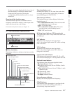
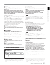
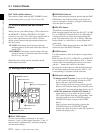
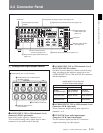
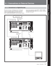
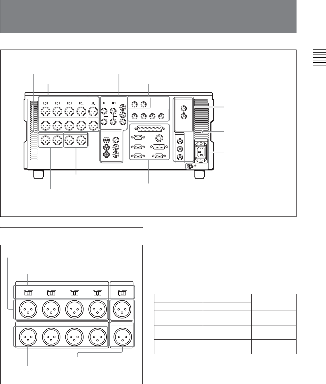
2-2 Connector Panel
75Ω 75Ω
Cooling fan
Cooling fan
1 Analog audio input/output
section
2 Analog video input/output section
(see page 2-16)
3 Digital audio input/output section
(see page 2-16)
4 Digital signal input/
output section
(see
page 2-17)
5 Power supply section
(see page 2-17)
6 External device connectors
(see page 2-17)
8 Audio monitor signal output section
(see
page 2-18)
7 Time code input/output
section
(see page 2-18)
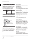
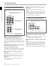
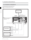
1 Analog audio input/output section
1 AUDIO INPUT CH1 to CH4 (channels 1 to 4)
connectors (XLR 3-pin, female)
Input analog audio signals to channels 1 to 4.
You can record analog audio signals input to these
connectors to any audio track on the tape.
AUDIO INPUT CUE
LOW
OFF
HIGH
ON
600Ω
CH1
LEVEL
LOW
OFF
HIGH
ON
600Ω
CH2
LEVEL
LOW
OFF
HIGH
ON
600Ω
CH3
LEVEL
LOW
OFF
HIGH
ON
600Ω
CH4
LEVEL
AUDIO OUTPUT CUE
CH1 OUTCH2 CH3 CH4
LOW
OFF
HIGH
ON
600Ω
IN
LEVEL
1 AUDIO INPUT CH1 to CH4 connectors
2 AUDIO INPUT CH1 to CH4 and CUE
IN LEVEL switches
3 AUDIO OUTPUT CH1 to
CH4 connectors
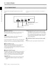
2 AUDIO INPUT CH1 to CH4 (channels 1 to 4)
and CUE IN LEVEL switches
Set these for each channel as shown in the following
table, according to the audio/cue input level to the
AUDIO INPUT CH1 to CH4 and CUE IN connectors
and the impedance.
AUDIO INPUT CH1 to CH4 and
CUE IN LEVEL switch settings
3 AUDIO OUTPUT CH1 to CH4 (channels 1 to 4)
connectors (XLR 3-pin, male)
These connectors output analog audio signals for
channels 1 to 4.
4 CUE IN/OUT(cue audio input/output)
connectors (XLR 3-pin, female/male)
The IN connector inputs and the OUT connector
outputs the analog cue audio signals.
Audio/cue input level and impedance Switch setting
Level
Impedance
–60 dBu
(microphone input)
High impedance
(approx. 20 kΩ)
LOW-OFF
(left position)
+4 dBu
(line audio input)
High impedance
(approx. 20 kΩ)
HIGH-OFF
(center position)
+4 dBm
(line audio input)
600Ω HIGH-ON 600Ω
(right position)
4 CUE IN/OUT connectors