


Chapter 2 Location and Function of Parts
Chapter 2 Location and Function of Parts 2-17
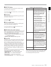
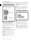
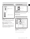
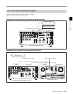
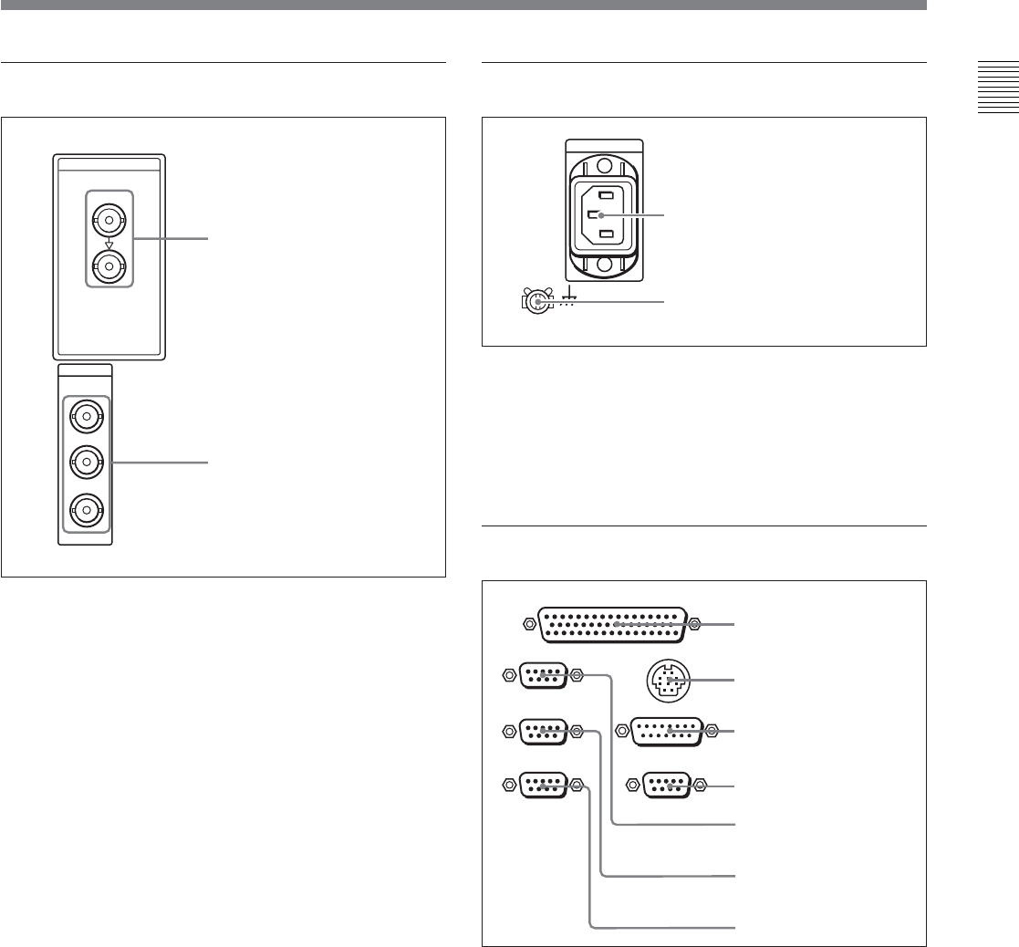
4 Digital signal input/output section
1 SDI (Serial Digital Interface) INPUT connectors
(BNC type)
Input D1 format digital video/audio signals. Of the two
connectors, the upper one is for input, and the lower
one is for an active-through connection.
2 SDI (Serial Digital Interface) OUTPUT
connectors (BNC type)
These connectors output D1 format digital video/audio
signals.
When the setting of F4 (CHARA) in function menu
page 4 is ON, connector 3 (SUPER) outputs a signal
with superimposed time code, menu settings, alarm
messages, and other text information.
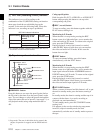
SDI
SDI
INPUT
OUTPUT
1
2
3(
SUPER
)
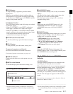
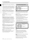
5 Power supply section
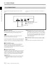
1 AC IN connector
Use a power cord to connect this to an AC outlet.
2 Ground terminal
Connect this to ground.
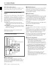
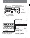
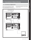
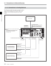
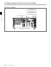
6 External device connectors
1 REMOTE 2 PARALLEL I/O(50P) connector
(D-sub 50-pin)
Connect remote control signals from an external
device.
For details, refer to the Installation Manual.
1 AC IN connector
2 Ground terminal
REMOTE 1-IN(9P)
CONTROL PANEL
REMOTE 2 PARALLEL I/O(50P)
VIDEO CONTROL
REMOTE 1-OUT(9P)
RS232C
(OPTION)
1 REMOTE 2 PARALLEL
I/O(50P) connector
2 CONTROL PANEL
connector
3 VIDEO CONTROL
connector
4 OPTION connector
5 REMOTE 1-IN(9P)
connector
6 REMOTE 1-OUT(9P)
connector
7 RS-232C connector
1 SDI INPUT connectors
2 SDI OUTPUT connectors