


GDM-F500/F500T9
– 5 –
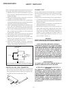
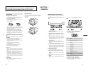
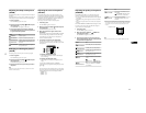
Note: Hand degauss must be used on stand-by or power-off condition.
This model has an automatic earth magnetism correction function by using an earth
magnetism sensor and a LCC coil. When using a hand degauss while monitor (LCC
coil) is being operated, it sometimes gets magnetized, and the system may not work
properly as a result.
TABLE OF CONTENTS
Section Title Page
1. GENERAL ................................................................. 1-1
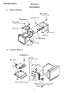
2. DISASSEMBLY
2-1. Cabinet Removal ............................................... 2-1
2-2. D Board Removal .............................................. 2-1
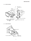
2-3. G Board Removal .............................................. 2-2
2-4. A Board Removal .............................................. 2-2
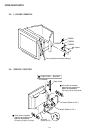
2-5. L Board Removal .............................................. 2-3
2-6. Service Position .................................................. 2-3
2-7. H1, H2 and J Boards Removal .......................... 2-4
2-8. US Board Removal............................................. 2-4
2-9. Picture Tube Removal ....................................... 2-5
2-10. Harness Location ................................................ 2-6
3. SAFETY RELATED ADJUSTMENT............. 3-1
4. ADJUSTMENTS ..................................................... 4-1
5. DIAGRAMS
5-1. Block Diagrams .................................................. 5-1
5-2. Frame Shcematic Diagram ................................. 5-7
5-3. Circuit Boards Location ..................................... 5-9
5-4. Schematic Diagrams and Printed Wiring
Boards ................................................................. 5-9
(1) Schematic Diagrams of D (1/2, 2/2) Board ...... 5-13
(2) Schematic Diagrams of G, H1, H2, J and
L Boards ............................................................ 5-17
(3) Schematic Diagram of A Board ........................ 5-24
(4) Schematic Diagram of US Board (-11)
(OLD) ................................................................ 5-29
(5) Schematic Diagram of US Board (-12, -13)
(NEW) .............................................................. 5-33
5-5. Semiconductors ................................................. 5-35
6. EXPLODED VIEWS
6-1. Chassis ............................................................... 6-1
6-2. Picture Tube ...................................................... 6-2
6-3. Packing Materials .............................................. 6-3
7. ELECTRICAL PARTS LIST ............................ 7-1