


SECTION 1
GENERAL
The operating instructions mentioned here are partial abstracts
from the Operating Instruction Manual. The page numbers of
the Operating Instruction Manual remain as in the manual.
1-1
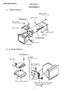
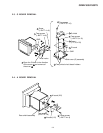
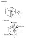
4
Precautions
Warning on power connections
• Use the supplied power cord. If you use a different power cord,
be sure that it is compatible with your local power supply.
For the customers in the U.S.A.
If you do not use the appropriate cord, this monitor will not
conform to mandatory FCC standards.
• Before disconnecting the power cord, wait at least 30 seconds
after turning off the power to allow the static electricity on the
screen’s surface to discharge.
• After the power is turned on, the screen is demagnetized
(degaussed) for about 3 seconds. This generates a strong
magnetic field around the screen which may affect data stored
on magnetic tapes and disks placed near the monitor. Be sure to
keep magnetic recording equipment, tapes, and disks away
from the monitor.
Installation
Do not install the monitor in the following places:
• on surfaces (rugs, blankets, etc.) or near materials (curtains,
draperies, etc.) that may block the ventilation holes
• near heat sources such as radiators or air ducts, or in a place
subject to direct sunlight
• in a place subject to severe temperature changes
• in a place subject to mechanical vibration or shock
• on an unstable surface
• near equipment which generates magnetism, such as a
transformer or high voltage power lines
• near or on an electrically charged metal surface
Maintenance
• Clean the screen with a soft cloth. If you use a glass cleaning
liquid, do not use any type of cleaner containing an anti-static
solution or similar additive as this may scratch the screen’s
coating.
• Do not rub, touch, or tap the surface of the screen with sharp or
abrasive items such as a ballpoint pen or screwdriver. This type
of contact may result in a scratched picture tube.
• Clean the cabinet, panel and controls with a soft cloth lightly
moistened with a mild detergent solution. Do not use any type
of abrasive pad, scouring powder or solvent, such as alcohol or
benzene.
Transportation
When you transport this monitor for repair or shipment, use the
original carton and packing materials.
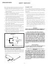
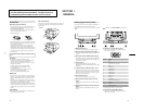
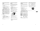
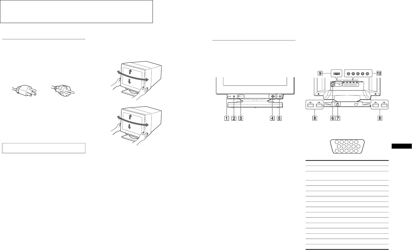
Use of the tilt-swivel
This monitor can be adjusted within the angles shown below. To
turn the monitor vertically or horizontally, hold it at the bottom
with both hands.
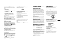
The equipment should be installed near an easily accessible
outlet.
Example of plug types
for 100 to 120 V AC for 200 to 240 V AC
90˚
5˚
90˚
12˚
GDM-F400
90˚
5˚
90˚
15˚
GDM-F500
5
EN
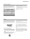
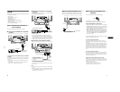
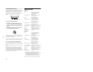
Identifying parts and controls
See the pages in parentheses for further details. GDM-F500 is
used for illustration purposes throughout this manual.
1
RESET button (page 14)
This button resets the adjustments to the factory settings.
2
ASC (auto sizing and centering) button (page 9)
This button automatically adjusts the size and centering of the
picture.
3
INPUT button and HD 15/BNC indicators (page 9)
This button selects the HD15 or BNC video input signal. The
input signal and corresponding input indicator change each
time you press this button.
4
Joystick (page 11)
The joystick is used to display the menu and make
adjustments to the monitor, including brightness and contrast
adjustments.
5
1
(power) switch and indicator (pages 7, 15, 18)
This button turns the monitor on and off. The power indicator
lights up in green when the monitor is turned on, and either
flashes in green and orange, or lights up in orange when the
monitor is in power saving mode.
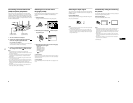
6
AC IN connector (page 7)
This connector provides AC power to the monitor.
7
USB (universal serial bus) upstream connector
(page 8)
Use this connector to link the monitor to a USB compliant
computer.
8
USB (universal serial bus) downstream connectors
(page 8)
Use these connectors to link USB peripheral devices to the
monitor.
9
Video input 1 connector (HD15) (page 6)
This connector inputs RGB video signals (0.700 Vp-p,
positive) and sync signals.
* DDC (Display Data Channel) is a standard of VESA.
q;
Video input 2 connector (BNC) (page 6)
This connector inputs RGB video signals (0.700 Vp-p,
positive) and sync signals.
(HD15) (BNC)
RGBHDVD
RESET ASC INPUT MENUHD15
BNC
RearFront
Pin No. Signal
1 Red
2 Green
(Composite Sync on Green)
3 Blue
4 ID (Ground)
5 DDC Ground*
6 Red Ground
7 Green Ground
8 Blue Ground
9 DDC + 5V*
10 Ground
11 ID (Ground)
12 Bi-Directional Data (SDA)*
13 H. Sync
14 V. Sync
15 Data Clock (SCL)*
5 4 3 2
1
6
78910
1112131415