


31
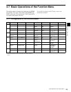
Basic Operations of the Function Menu
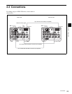
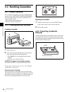
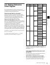
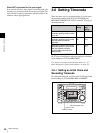
Chapter 3 Preparations
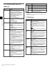
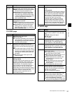
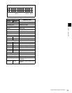
P2 VIDEO page
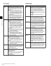
P3 AUDIO page
SETUP/
BLACK
Sets the setup level (59.94i mode) or black
level (50i mode) of the HD/SD output signal.
PRESET: Regardless of manually set values,
the level is set to the standard value.
Manual setting: With the displayed setting
flashing, you can adjust the setup level
across the range ±30 IRE (59.94i mode)
or adjust the black level across the range
±210 mV (50i mode) by rotating the
MULTI CONTROL knob.
Y/C DELY Sets the Y/C delay during playback of an
analog Betacam cassette.
PRESET: Regardless of manually set values,
the Y/C delay is set to the standard value.
Manual setting: With the displayed setting
flashing, you can adjust the Y/C delay
across the range ±100 ns by rotating the
MULTI CONTROL knob.
Item Setting
VIDEO IN Selects the input video signal.
SDI: HD SDI signal
SG: Test signal generated by the internal test
signal generator (To select SG, hold the
corresponding function button pressed for
more than three seconds.)
OUT REF Selects the reference signal of this unit,
according to the settings of setup menu items
309 and 334, and the operating state of this
unit.
REF: Use the signal input to the REF INPUT
connector as the reference signal. During
recording, input digital audio signals and
video signals must be synchronized with
this signal.
INPUT: Use the input video signal as the
reference signal.
SYNC Sets the SD/HD output signal sync phase.
Setting method
Press the SYNC function button then rotate
the MULTI CONTROL knob to adjust the
output signal sync phase with the displayed
setting flashing. The adjustable range is
±15 µs relative to the input reference signal.
Adjust this item if you wish to adjust the
output signal sync phase precisely to match a
reference signal or when connecting this unit
and other VTRs to a device such as a
switcher to perform operations such as
special effects editing.
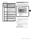
Item Setting
SC Sets the SD/HD output signal subcarrier
phase.
Setting method
Press the SC function button then rotate the
MULTI CONTROL knob to adjust the output
signal subcarrier phase with the displayed
setting flashing. The adjustable range is
±200 ns relative to the input reference signal.
Adjust this item when you are using
composite signals in editing and wish to
adjust the output signal subcarrier phase
precisely to match a reference signal. Even
when this value is adjusted, the output SCH
(subcarrier to sync) phase is maintained.
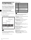
Item Setting
AUDIO IN Selects an audio input signal. The selected
signal is shown at INPUT in the audio data
area.
ANALOG: Analog audio signal
SDI: SDI signal
SG: SG signal
MONITR L Selects an output signal from the AUDIO
MONITOR OUTPUT L connector (CH1/CH2/
CH3/CH4/CUE). The selected signal is
shown at MONI L in the audio data area.
MONITR R Selects an output signal from the AUDIO
MONITOR OUTPUT R connector (CH1/CH2/
CH3/CH4/CUE). The selected signal is
shown at MONI R in the audio data area.
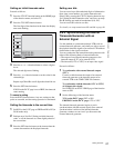
LEVEL MT Sets the audio level meter displayed on the
video monitor display.
LEFT: Display the audio level meter on the
left of the video monitor display.
RIGHT: Display the audio level meter on the
right of the video monitor display.
LEFT (4): Displays the four-channel audio
level meters on the left of the video
monitor display.
RIGHT (4): Displays the four-channel audio
level meters on the right of the video
monitor display.
OFF: Not display the audio level meter.
EMPHASIS Specifies whether to add audio emphasis to
analog audio input signals and Betacam/
Betacam SP format playback audio signals.
ON: Add audio emphasis.
OFF: Do not add audio emphasis.
DOLBY NR When using oxide tapes, this is to specify
whether or not to use the Dolby type C low-
frequency noise reduction (NR) system.
ON: Use the Dolby NR system when playing
back analog Betacam oxide tapes.
OFF: Do not use the Dolby NR system when
playing back analog Betacam oxide tapes.
Item Setting