


12
KV-27FS320/32FS120/32FS320/34FS120/36FS120/36FS320/38FS120
KV-27FS320/32FS120/32FS320/34FS120/36FS120/36FS320/38FS120
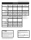
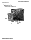
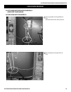
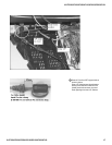
1. Discharge the anode of the CRT and remove the
anode cap.
2. Unplug all interconnecting leads from the
defl ection yoke, neck assembly, degaussing coils
and CRT grounding strap.
3. Remove the C Board from the CRT.
4. Remove the chassis assembly.
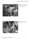
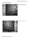
5. Loosen the neck assembly fi xing screw and
remove.
6. Loosen the defl ection yoke fi xing screw and
remove.
7. Place the set with the CRT face down on a
cushion and remove the degaussing coil holders.
8. Remove the degaussing coils.
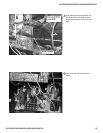
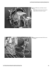
9. Remove the CRT grounding strap and spring
tension devices.
10. Unscrew the four CRT fi xing screws [located on
each CRT corner] and remove the CRT [Take
care not to handle the CRT by the neck].
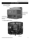
1-4. PICTURE TUBE REMOVAL
WARNING: BEFORE REMOVING THE ANODE CAP
High voltage remains in the CRT even after the power is disconnected. To avoid electric shock,
discharge CRT before attempting to remove the anode cap. Short between anode and CRT
coated earth ground strap.
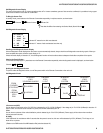
ANODE CAP REMOVAL PROCEDURE
WARNING: High voltage remains in the CRT even after the power is disconnected. To avoid electric shock, discharge CRT before attempting to
remove the anode cap. Short between anode and coated earth ground strap of CRT.
NOTE: After removing the anode cap, short circuit the anode of the picture tube and the anode cap to either the metal chassis, CRT shield, or carbon
painted on the CRT.
REMOVAL PROCEDURES
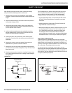
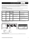
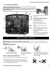
HOW TO HANDLE AN ANODE CAP
1. Do not use sharp objects which may cause damage to the surface of the anode
cap.
2. To avoid damaging the anode cap, do not squeeze the rubber covering too
hard. A material fi tting called a shatter-hook terminal is built into the rubber.
3. Do not force turn the foot of the rubber cover. This may cause the shatter-hook
terminal to protrude and damage the rubber.
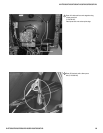
Turn up one side of the rubber cap in
the direction indicated by arrow
a
.
Use your thumb to pull the rubber
cap fi rmly in the direction indicated
by arrow
b
.
When one side of the rubber cap separates from
the anode button, the anode cap can be removed
by turning the rubber cap and pulling it in the
direction of arrow
c
.
a
b
Anode Button
c
10
4
1
9
8
7
6
5
2
3