


3
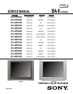
KV-27FS320/32FS120/32FS320/34FS120/36FS120/36FS320/38FS120
KV-27FS320/32FS120/32FS320/34FS120/36FS120/36FS320/38FS120
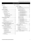
TABLE OF CONTENTS
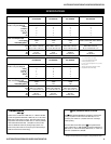
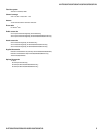
Specifi cations ................................................................................. 4
Warnings and Cautions .................................................................. 6
Safety Check-Out ........................................................................... 7
Self-Diagnostic Function................................................................. 8
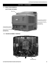
SECTION 1: DISASSEMBLY............................................................... 10
1-1. Rear Cover Removal............................................................ 10
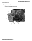
1-2. Chassis Assembly Removal................................................. 10
1-3. Service Position ...................................................................11
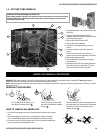
1-4. Picture Tube Removal.......................................................... 12
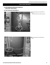
Anode Cap Removal Procedure........................................... 12
Cable Wire Dressing ............................................................ 13
KV-27FS320/32FS320/36FS320 Models........................ 13
KV-32FS120/34FS120 Models ....................................... 13
KV-36FS120/38FS120 Models ....................................... 18
SECTION 2: SET-UP ADJUSTMENTS................................................ 23
2-1. Beam Landing...................................................................... 23
2-2. Convergence........................................................................ 24
2-3. Focus ................................................................................... 25
2-4. Screen (G2).......................................................................... 26
2-5. Method of Setting the Service Adjustment Mode ................. 26
2-6. White Balance Adjustments ................................................. 26
SECTION 3: SAFETY RELATED ADJUSTMENTS............................. 27
3-1.
X
R530, R531 Confi rmation Method (HV Hold-Down
Confi rmation) and Readjustments........................................ 27
3-2. B+ Voltage Confi rmation and Adjustment ............................ 27
SECTION 4: CIRCUIT ADJUSTMENTS.............................................. 28
4-1. Setting the Service Adjustment Mode .................................. 28
4-2. Memory Write Confi rmation Method .................................... 28
4-3. Remote Adjustment Buttons and Indicators......................... 28
4-4. Service Data Lists ................................................................ 29
KV-27FS320 Service Data ................................................... 29
KV-32FS320 Service Data ................................................... 30
KV-36FS320 Service Data ................................................... 39
KV-32FS120/34FS120 Service Data.................................... 48
KV-36FS120/38FS120 Service Data.................................... 57
4-5. ID Map Table........................................................................ 57
4-6. A Board Adjustments............................................................ 58
SECTION 5: DIAGRAMS..................................................................... 61
5-1. Circuit Boards Location........................................................ 61
5-2. Printed Wiring Board and Schematic Diagram Information.. 61
5.3. Block Diagram and Schematics ........................................... 62
A Board Schematic Diagram (1 of 2).................................... 63
A Board Schematic Diagram (2 of 2).................................... 64
HM Board Schematic Diagram (1 of 4)
(KV-27FS320/32FS320/36FS320 Only) .................. 66
HM Board Schematic Diagram (2 of 4)
(KV-27FS320/32FS320/36FS320 Only) .................. 67
HM Board Schematic Diagram (3 of 4)
(KV-27FS320/32FS320/36FS320 Only) .................. 68
HM Board Schematic Diagram (4 of 4)
(KV-27FS320/32FS320/36FS320 Only) .................. 68
V Board Schematic Diagram ............................................... 69
M Board Schematic Diagram ............................................... 70
C Board Schematic Diagram ............................................... 72
HN Board Schematic Diagram
(KV-27FS320/32FS320/36FS320 Only) .................. 73
HR Board Schematic Diagram
(KV-27FS320/32FS320/36FS320 Only) .................. 73
HS Board Schematic Diagram
(KV-32FS120/34FS120/36FS120/38FS120 Only)... 73
HU/HD Board Schematic Diagram
(KV-27FS320/32FS320/36FS320 Only) .................. 76
5-4. Semiconductors ................................................................... 79
SECTION 6: EXPLODED VIEWS........................................................ 80
6-1. Chassis
(KV-27FS320/32FS320/36FS320 Only)............................... 80
6-2. Picture Tube
(KV-27FS320/32FS320/36FS320 Only)............................... 81
6-3. Chassis
(KV-32FS120/34FS120/36FS120/38FS120 Only) ............... 82
6-4. Picture Tube
(KV-32FS120/34FS120/36FS120/38FS120 Only) ............... 83
SECTION 7: ELECTRICAL PARTS LIST........................................... 84
SECTION TITLE PAGE SECTION TITLE PAGE