


6
FE-2 SELF DIAGNOSTIC SOFTWARE
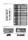
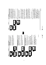
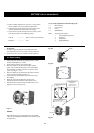
The identification of errors within the FE-2 chassis is triggered in one of two ways :- 1: Busy or 2: Device failure to respond to IIC. In the event of
one of these situations arising the software will first try to release the bus if busy (Failure to do so will report with a continuous flashing LED) and
then communicate with each device in turn to establish if a device is faulty. If a device is found to be faulty the relevant device number will be
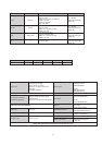
displayed through the LED (Series of flashes which must be counted) See table 1., non fatal errors are reported using this method.
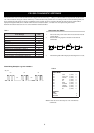
Each time the software detects an error it is stored within the NVM. See Table 2.
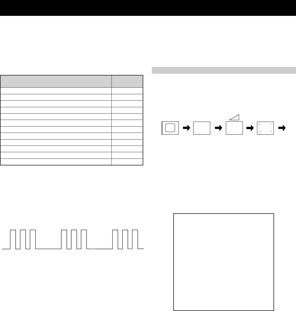
Flash Timing Example : e.g. error number 3
StBy LED
ON
ON ON
OFF
OFF
egasseMrorrE
DEL
edoC
rorreoN00
devreseR10
)noitcetorPtnerruCrevO(PCO20
devreseR30
cnySlacitreVoN40
BKAelbatsnU50
norewoptawolsenilatadro/dnakcolcsubCII60
norewoptaegdelwonkcasubCIIonMVN70
desUtoN80
norewoptaegdelwonkcaonrenuT90
desutoN01
NOrewoPtaegdelwonkcaonrellortnocelgnuJ11
Table 1
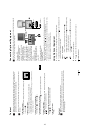
How to enter into Table 2
1. Turn on the main power switch of the TV set and enter into the
‘Stanby Mode’.
2. Press the following sequence of buttons on the Remote
Commander.
i+
5
-
(ON SCREEN (DIGIT 5) (VOLUME -) (TV)
DISPLAY)
3. The following table will be displayed indicating the error count.
Table 2
Note: To clear the error count data press ‘80’ on the Remote
commander.
UNEMRORRE
20E
30E
40E
50E
60E
70E
80E
90E
01E
11E
GNIKROW
EMIT
SRUOH
SETUNIM
PCO
A/NPVO
CNYSV
RKI
CII
MVN
ELGNUJ
RENUT
PDNUOS
V8
)552,0(
)552,0(
)552,0(
)552,0(
)552,0(
)552,0(
)552,0(
)552,0(
)552,0(
)552,0(
0
0
0
0
0
0
0
0
0
0
0
0