


– 3 –
KV-PF21M70/TF21M61/TF21M90/TF21P11
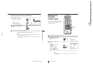
RM-952
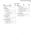
TABLE OF CONTENTS
Section Title Page
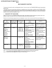
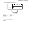
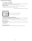
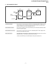
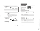
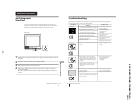
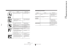
SELF DIAGNOSIS FUNCTION................................ 3
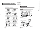
1. GENERAL .......................................................... 8
2. DISASSEMBLY
2-1. Rear Cover Removal................................................ 32
2-2. Chassis Assy Removal............................................. 32
2-3. F Bracket Removal .................................................. 32
2-4. Service Position ....................................................... 33
2-5. Replacement of Parts............................................... 33
2-5-1. Replacement of Control Button ....................... 33
2-5-2. Replacement of Bar Control............................. 33
2-6. Terminal Bracket Removal ...................................... 33
2-7. Degauss Coil Removal............................................. 34
2-8. Picture Tube Removal.............................................. 34
3. SET-UP ADJUSTMENTS
3-1. Beam Landing.......................................................... 36
3-2. Convergence............................................................. 37
3-3. Focus Adjustment .................................................... 39
3-4. G2 (Screen) and White Balance Adjustments......... 39
4. CIRCUIT ADJUSTMENTS
4-1. Adjustments with Commander................................ 40
4-2. Adjustment Method ................................................. 41
4-3. Picture Quality Adjustments.................................... 46
4-4. A Board Adjustment After IC003 (Memory)
Replacement............................................................. 46
4-5. Picture Distortion Adjustment ................................. 47
Section Title Page
5. DIAGRAMS
5-1 Block Diagram......................................................... 59
5-2 Frame Schematic Diagram ...................................... 62
5-3 Circuit Boards Location .......................................... 64
5-4 Schematic Diagrams and Printed Wiring Boards ... 65
(1) Schematic Diagram of A(1/2) Board....................... 67
(2) Scheamtic Diagram of A(2/2) Board....................... 71
(3) Schematic Diagrams of C3 and C5 Boards............. 79
(4) Schematic Diagram of V1 Board ............................ 85
(5) Schematic Diagram of F Board ............................... 87
5-5 Semicondutors ......................................................... 90
6. EXPLODED VIEWS
6-1. Chassis (KV-PF21M70)........................................... 93
6-2 Chassis (KV-TF21M61/TF21M90/TF21P11)......... 95
7. ELECTRICAL PARTS LIST................................... 97