


6-1
SLV-LX40/LX50/LX60S/LX70S
6-1 MECHANICAL ADJUSTMENTS
For the mechanical adjustments, please refer to the
“VHS MECHANICAL ADJUSTMENT MANUAL
(S MECHANISM)” (9-921-647-11).
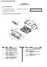
6-2. ELECTRICAL ADJUSTMENTS
See the adjusting part location diagram from on page 6-6
for the adjustment.
2-1. PREPARATION BEFORE ADJUSTMENT
2-1-1. Equipment Required
The measuring instruments used for this alignment include:
1) Monitor TV
2) Oscilloscope, dual-trace, bandwidth of 30 MHz or more, with
delay mode (A probe 10:1 should be used unless otherwise
specified.)
3) Frequency counter
4) NTSC Pattern generator
5) Remote commander
6) Digital voltmeter
7) Audio generator
8) Audio level meter
9) Audio attenuator
10) Alignment tapes
KRV-51N2 (NTSC) Part No. : 8-192-605-32
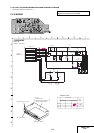
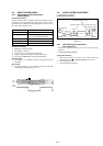
2-1-2. Equipment Connection
Unless otherwise specified, connect and adjust the measuring
instruments as shown in the following diagram.
Fig. 6-2-1
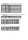
2-1-3. Set-up of Adjustment
In this adjustment, NTSC pattern generator is connected with LINE
input terminal. When check to tuner, connected AERIAL terminal.
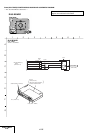
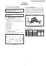
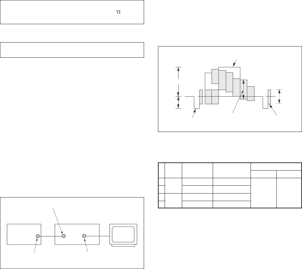
Check that the synchronizing signal of the Y signal has an amplitude
of approximately 0.7 V and that the burst signal has an amplitude of
approximately 0.3 V and its waveform is flat. And check that the
level ratio of burst signal to “red” signal is 0.30 : 0.66. The video
signal (color bar) used for electrical aligning this unit is shown in
Fig. 6-2-2.
NTSC model
Fig. 6-2-2 Color Bar Signals of Pattern Generator
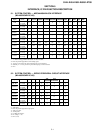
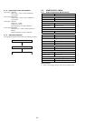
2-1-4. Alignment Tape
• Contents of KRV-51N2
VIDEO LINE IN
VIDEO LINE OUT
Video output
(75Ω)
Pattern generator VCR
Monitor TV
1
2
3
4
Mode
SP
LP
Period
7 minutes
3 minutes
7 minutes
3 minutes
Video signal
Color bar
Monoscope
Color bar
Monoscope
Audio signal
Hi-Fi
400Hz
(L/R)
Normal
400Hz
White (100%)
About 0.7 V
About
0.3 V
Horizontal sync signal
Red
Burst signal
(It must be flat.)
About
0.3 V
SECTION 6
ADJUSTMENTS