


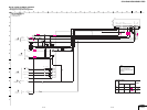
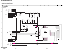
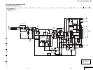
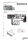
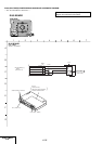

5-3
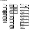
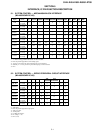
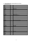
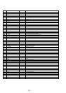
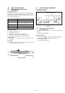
5-7. SERVO/SYSTEM CONTROL MICROPROCESSOR PIN FUNCTIONS
(MA-405 BOARD IC160)
Pin No.
1
2
3
4
5
6
7
8
9
10
11
12
13
14
15
16
17
18
19
20
21
22
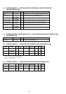
23
24
25
26
27
28
29
30
31
32
33
34
35
36
37
38
39
40
41
42
43
44
45
46
47
48
49
50
Pin Name
DEST
MPX MODE
TU AFT
FUNC KEY2
FUNC KEY1
S SENS
T SENS
V RF ENV
AF ANV
CBC ON
KKP+
KKP–
QVD
REMOCON
C ROT
HA SWP
ENV SW
RF SWP
AF SWP
END LED
ANT SEL
AF REC P
FE ON
CAP RVS
SUR ON
MODE4
MODE3
MODE2
MODE1
REC PRF
I2C CLK EEP
I2C DATA EEP
CAM
RESET
32kHz (in)
32kHz (out)
Vcc
4fsc (in)
4fsc (out)
Vss
ARC CLK
ARC DATA
CLK SEL
OSC IN
OSC OUT
NUB
LPF
SP
OSD GND
OSD V IN
I/O
I
I
I
I
I
I
I
I
I
O
I
I
O
I
O
O
I
O
O
O
O
O
—
O
—
I
I
I
I
I
I/O
I/O
O
I
I
O
I
I
O
—
O
O
I
I
O
—
I/O
O
—
I
Function
Destination control input
STEREO/MONO/SAP DETECTION
Tuner analog AFT input
Key input
Key input
Tape end sensor input
Tape top sensor input
Video playback signal envelope input
Hi-Fi audio playback signal envelope input
Cable box control signal output
ETR pulese signal input
ETR pulese signal input
Quasi VD pulese output
Remote sires signal input
Head AZ signal output
SP/EP changed head signal
SP/EP head output lebel ditaction signal
VIDEO RF switching pulse output.
AF switching pulse output.
END sensor LED output
TV/VTR RF modulator control output
Hi-Fi record control pulse output.
NC
Capstan reverse control
NC
Mechanism section CAM encoder input (data4)
Mechanism section CAM encoder input (data3)
Mechanism section CAM encoder input (data2)
Mechanism section CAM encoder input (data1)
Erasing protection tab, cassette IN detection input
HC CLOCK line (EEPROM)
HC DATA line (EEPROM)
Cam motor control signal output
System reset input
Sub clock 32MHz
Sub clock 32MHz
5V
Main clock input
Main clock output
Ground
Realityregenarator (ARC) control clock signal
Realityregenarator (ARC) control data signal
CLOCK seleal “L” Sub clock, “H” main and sub clock.
OSD clock input
OSD clock output
Ground
fsc filter
“L” output when SP mode.
Ground
OSD Video signal input.