


1-17
67
General setup information
Additional Information
General setup information
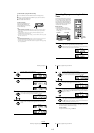
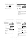
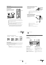
Setting the RF unit
When connecting the VCR to the TV using
only the antenna cable, you must set the RF
UNIT switch on the rear of the VCR so that
the TV can receive the correct signal from
the VCR.
1
Set the RF UNIT switch on the rear of the VCR to CH3 or CH4, whichever
channel is not used in your area. If both are used, set the switch to either channel.
2
Press ?/1 POWER to turn on the VCR.
3
Press TV/VIDEO to turn on the VIDEO indicator in the VCR’s display window.
4
Press CHANNEL +/– to display a channel number in the display window.
Select an active channel number in your area.
5
Turn on your TV and set it to the channel you selected in step 1 (channel 3 or 4).
The channel you selected in step 4 appears on the TV screen. If the channels
change when you press CHANNEL +/–, you have made the correct setting.
Whenever you use the VCR, set the TV to the channel selected in step 1.
CH3
RF UNIT
CH4
TV
CHANNEL +/–
?
/
1
POWER
123
456
789
0
TV/VIDEO
continued
68
General setup information
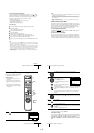
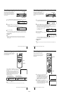
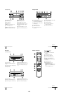
Attaching the external antenna connector
Attaching a UHF/VHF band mixer
When using a 300-ohm twin lead cable for a
VHF/UHF antenna, use the EAC-32 antenna
connector (not supplied) to connect the
antenna to the VCR.
1
Loosen the screws on the antenna connector.
2
Wind the twin leads around the screws on the antenna connector.
3
Retighten the screws.
When using both a 75-ohm coaxial cable and
a 300-ohm twin lead cable for a VHF/UHF
antenna, use the EAC-66 UHF/VHF band
separator/mixer (not supplied) to connect the
antenna to the VCR.
1
Loosen the screws on the mixer.
2
Wind the twin leads around the screws on the mixer.
3
Retighten the screws.
4
Connect the 75-ohm coaxial cable to the mixer.
300-ohm twin
lead cable
EAC-32 antenna
connector (not
supplied)
300-ohm twin
lead cable
EAC-66
UHF/VHF
band
separator/
mixer (not
supplied)
75-ohm coaxial
cable
71
Troubleshooting
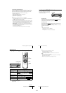
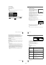
Head Condition Sensor
The Head Condition Sensor checks the video heads’ condition. If the heads are dirty, a message
will instruct you to insert a video head cleaning cassette.
Be sure to use the Sony T-25CLD or T-25CLDR video head cleaning cassette. If these cleaning
cassettes are not available in your area, have the heads cleaned at your nearest Sony service
facility (a standard service charge will be required).
Note
• SENSR CONDCIÓN CABEZA in OPCIONES must be set to SI for the Head Condition
Sensor to operate.
• To turn off the head condition sensor message, set SENSR CONDCIÓN CABEZA to NO.
Symptoms caused by contaminated video heads
•Normal picture •Unclear picture•Rough picture
initial
contamination
terminal
•No picture (or
black & white
screen appears)
73
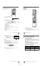
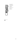
Index to parts and controls
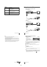
Index to parts and controls
Refer to the pages indicated in parentheses ( ) for details.
Front panel
SLV-LX70S and LX60S
A ?/1 POWER switch (44)
B Z EJECT button (33)
C Tape compartment
D Remote sensor (5)
E m REW (rewind) button (33) (47)
F H PLAY button (33) (47)
G M FF (fast-forward) button (33) (47)
H z REC (record) button (36) (49) (66)
I x STOP button (33) (66)
J X PAUSE button (33) (66)
K DIAL TIMER (38) (54) (55) (56)
L SEARCH MODE button (54) (55) (56)
M CHANNEL/TRACKING +/– buttons
(36) (60)
N EASY SET UP button (11) (13) (16)
O LINE-2 IN VIDEO/AUDIO L/R jacks
(64)
continued