


6-4
2-4-3. Normal Audio System Adjustment
• Make adjustment in the SP mode unless otherwise specified. Use
a normal VHS cassette for an adjustment tape.
• Set AUDIO MONITOR to normal.
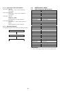
2-4-4. Audio Level and Distortion Check
[Adjustment purpose]
Confirm that the audio level and distortion is within the specification.
Mode REC and PB (SP mode)
Signal 400 Hz, –7.5 dBs
Measurement point Audio output terminal
Measuring instrument Audio level meter and distortion
meter
Specified value PB level : –7.5±2dBs (HIFI)
PB level : –7.5±3dBs (MONO)
Distortion : less than 1% (HIFI)
Distortion : less than 4% (MONO)
[Confirmation Method]
1) Supply a signal of 400 Hz, –7.5 dBs to both L and R channels
of Audio Line Input.
2) Record the tape.
3) Playback a recorded portion of the tape.
4) Confirm that the playback output level of audio level meter is
within of range –7.5±2dBs for HIFI and –7.5±3dBs for MONO.
5) Confirm that the output of distortion meter is less than 1% for
HIFI and 4% for MONO.
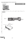
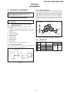
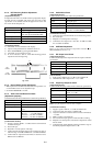
2-4-2. HiFi Switching Position Adjustment
(MA-405 Board)
[Adjustment Purpose]
To adjust the link of the A-ch and B-ch of the tape playback outputs.
To make the unit compatible with other tapes and units. If this
specification is not satisfied, the link will appear on the screen and
the screen will be disrupted, etc.
Mode Playback
Signal Alignment tape: SP color bar portion
Measurement point CH1: Pin 1 of CN270 (HF ADJ)
CH2: Pin 3 of CN270 (RF SWP)
Measuring instrument Oscilloscope
Adjusting element Remote Commander CH +/–
Specified value B=minimize
[Adjustment Method]
1) Check that “A H” is indicated on FL display.
2) Adjust so that part B becomes minimized at CH +/–.
3) Write data EEPROM by pressing PAUSE button.
4) Check that “A H” indicator turns off.
5) If “A H” indicator is still on, restart RF switching position
Adjustment from the beginning.
Fig. 6-2-5
CH1
HFADJ
CH2
RF SWP
B
2-4-5. Audio Noise Check
[Adjustment purpose]
Confirm that the noise level is within the specification.
Mode REC and PB (SP mode)
Signal No signal input
Measurement point Audio output terminal
Measuring instrument Audio level meter
Specified value Less than –67,5dBs (HIFI)
Less than –45.5dBs (MONO)
[Confirmation method]
1) Audio line input L and R channels are shorted to the ground.
2) Record the tape.
3) Playback a recorded portion of the tape.
4) Confirm that the output level is less than –67.5dBs for HIFI
and –45.5dBs for MONO.
2-4-6. ACE Head Adjustment
Refer to the VHS mechanical adjustment manual
(S
MECHANISM) (9-921-647-11).
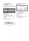
2-4-7. E-E Output Level Check
[Adjustment purpose]
Confirm that the output level adjust the reference input is within the
specification.
Mode E-E
Signal 400 Hz, –7.5 dBs
Measurement point CNJ562 L/R
Measuring instrument Audio level meter
Specified value –7.5 ± 2 dBs
[Check Method]
1) Input signal of 400 Hz and –7.5 dBs to the CNJ562 L/R.
2) Check that the audio output level is –7.5 ± 2 dBs.
2-4-8. Frequency Response Check
[Adjustment purpose]
Confirm that the frequency characteristic is within the specification.
Mode REC and PB (SP mode)
Signal 400 Hz, –17.5 dBs
7 kHz, –17.5 dBs
Measurement point CNJ562 L/R
Measuring instrument Audio level meter
Specified value 0 ± 3 dB
Note: Tape path adjustment must have been completed.
[Confirmation Method]
1) Supply a signal of 400 Hz, –17.5 dBs to CNJ562 L/R.
2) Connect the audio level meter to CNJ562 L/R.
3) Adjust the attenuator so that the audio level meter will indicate
–17.5 dBs.
4) Make recording in the SP mode.
5) Set an audio line input signal to 7 kHz and make recording.
6) Playback a recorded portion, and measure output levels at 400
Hz and 7 kHz.
7) Confirm that the 7 kHz playback output level within a range of
the 400 Hz playback output level 0 ± 3 dB.