


11
DVD Technical Notes
Video
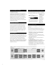
Many of the video equalizer adjustments exist to tailor perform-
ance for individual DVDs. That’s why the DVP-S9000ES can
store your favorite settings for instant recall. Custom Memory
lets you store five standard settings for different movie studios,
different DVD genres or different types of display. Playback
Memory stores your fine-tuned adjustments for up to 300 discs.
Each time you insert one of the 300 discs, the player will
automatically recall your specific hand-tailored adjustments.
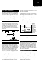
The master clock resides in the Audio section. But instead of
passively receiving the external clock signal, the video circuit
regenerates its own 27 MHz reference clock with its own quartz
crystal. This reference is distributed to every digital video
circuit. So timing errors and their consequent distortions are
kept to a bare minimum. Images achieve maximum stability and
minimum jitter.
One natural consequence of supplying both progressive and
interlaced video outputs is the need to provide both progressive
and interlaced video D/A converters. DVP-S9000ES is equipped
with both video D/A coverters, one for interlace output and the
other for progressive output. The DVP-S9000ES progressive
D/A converter was developed in cooperation with Analog
Devices Corp., the same company that built the 32-bit SHARC
processor in Sony’s TA-E9000ES A/V digital preamplifier.
This is a Large Scale Integrated circuit (LSI) of remarkable
processing power. Sony’s previous designs converted the DVD’s
8-bit video samples with 10 bits of precision. This current LSI
raises the standard of performance with 12-bit conversion for the
luminance (Y) signal and 11-bit conversion for each of the color
difference signals (C
B
and C
R
). Higher word lengths enable four
times the fine gradations in the luminance channel, and twice as
many gradations in each of the color channels. So you get a
more accurate rendition of colors and gray scale from the deepest
black to the brightest highlights.
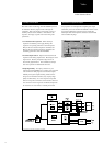
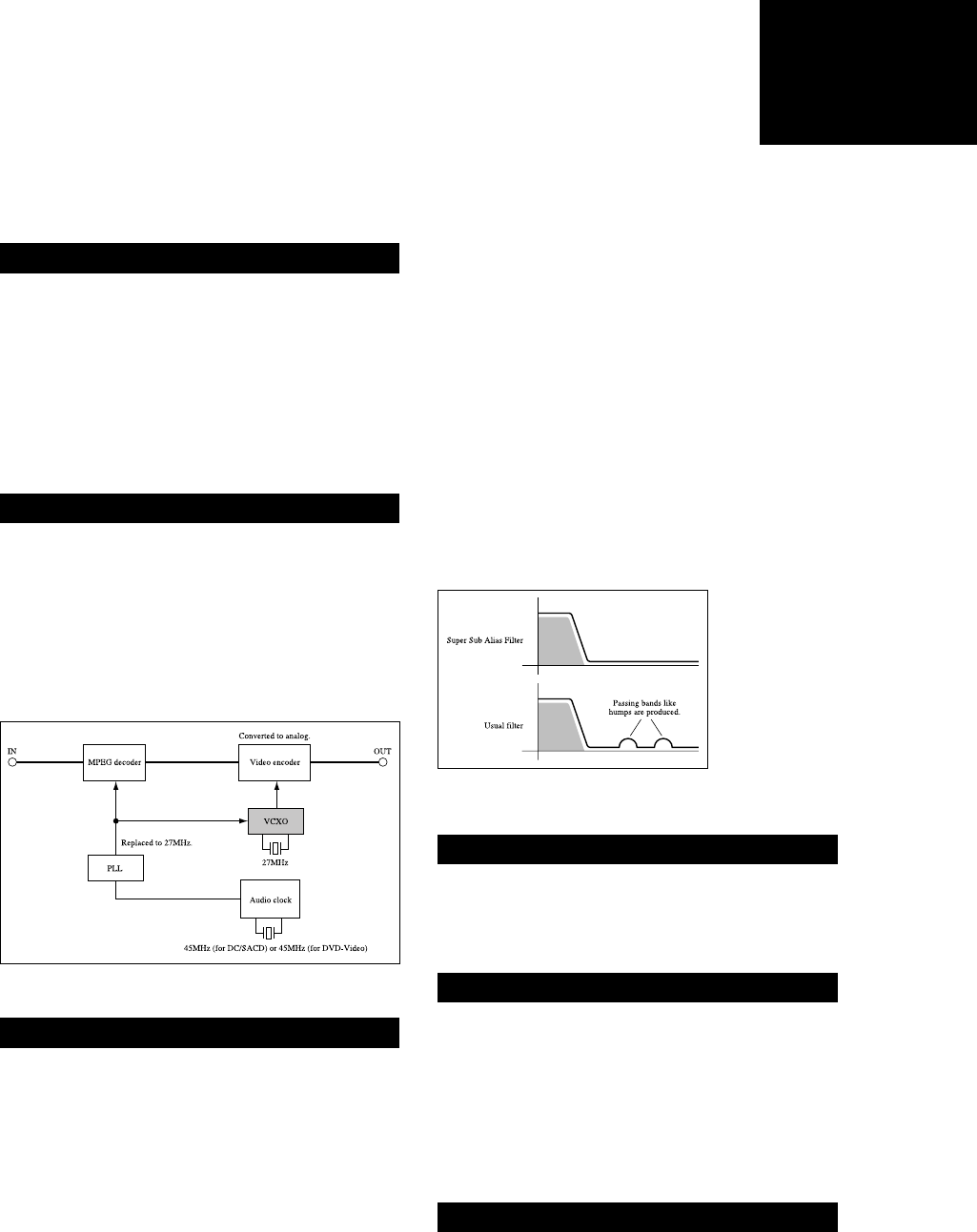
In addition, the converter employs video oversampling similar to
the oversampling near universal in audio CD players. To capture
13.5 MHz signals, the luminance channel uses a 27 MHz
sampling frequency. The D/A conversion uses 2x oversampling
system to bring this to 54 MHz. In a similar process, each
chrominance channel gets 4x oversampling. The C
B
and C
R
sampling frequency of 13.5 MHz is quadrupled to 54 MHz. As
in CD players, this method makes quantization noise easier to
filter out, with more linear amplitude frequency response within
the passband and superb suppression of noise outside the
passband. As incorporated in the Analog Devices Super Sub
Alias Filter
TM
design, this
achieves better
signal-to-noise
ratio and superb
frequency
response, taking
DVD 4:2:2 D/A
converters into the
realm of 8:8:8
performance.
Separate video filters for progressive and interlaced outputs help
achieve wide bandwidth, high resolution and minimum out-of-
band noise.
The interlaced output must pass 6.75 MHz, while the progressive
output must achieve twice that frequency — 13.5 MHz. Since
bandwidth equates to resolution, the DVP-S9000ES is equipped
with high-speed video buffer amplifiers that are more than equal
to the task. These circuits can pass 325 MHz without loss. As
such, the buffer amps are prepared to drive capacitive cable runs,
while minimizing such distortions.
In typical audio and video design, an output capacitor prevents
the accidental passing of DC offset voltage from one component
to the next. However, the mere presence of the output capacitor
can affect the audio frequency response and literally tinge the
television picture with unwanted shading. And these effects are
beyond the adjustment of your television’s video adjustments.
Sony’s answer is a rigorous design that controls DC offset
voltages from the start. You get reliable operation without
performance-robbing output capacitors.
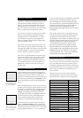
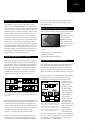
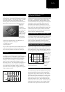
Video Clock and Video Data TBC
Fig.12: A dedicated 27 MHz quartz crystal oscillator regenerates a
super-clean video-only reference clock.
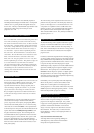
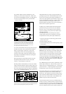
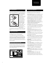
54 MHz Video D/A Converter
Fig. 13: The Super Sub Sampling Alias Filter (top) controls
the noise of alias signals (bumps on bottom).
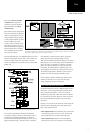
Optimized Video Filters
High-Speed Video Buffers
Output Capacitor-Less (OCL) Coupling
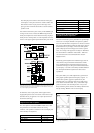
Custom Memory / Playback Memory