


12
More than a labor of technology, the DVP-S9000ES represents
the enthusiasm that Sony engineers share with high-end
videophiles. That’s why the player incorporates a variety of
carefully selected resistors, inductors, semiconductors and
capacitors. Each plays a specific role in maximizing video
performance.
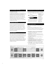
• Low Distortion Film Capacitors. While electrolytic
capacitors are suitable to power supply filtering, film
capacitors are especially proficient for sound and picture.
Many of these low-distortion capacitors contribute to the
Many of these low-distortion capacitors contribute to the
outstanding performance of the DVP-S9000ES.
• Oversized output resistors. Output resistors determine the
impedance of the analog output circuits. Most designers avoid
large resistors. But Sony incorporates large resistors of
uncommonly tight tolerances. This contributes to the high
slew rates required for wideband audio and video.
• Output Signal Relay. To simplify connections to your
television, the DVP-S9000ES uses a common set of component
video terminals for both progressive and interlaced output.
Naturally, this requires output switching. While common
designs use semiconductor switches, Sony employs a high-
quality mechanical relay. It’s a more expensive design that
delivers more positive connections, lower resistance and lower
noise across the switch. Progressive and interlaced output can
be selected via on-screen menus or via back panel switch.
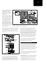
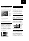
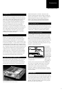
Sony engineers even anticipated the videophile-grade output
cables likely to be used with the DVP-S9000ES. For this reason,
the engineers deliberately spaced the Y/C
B
/C
R
output jacks
further apart than common practice, the better to accommodate
extra-fat cables and plugs!
Wide Pitch Component Output
Photo 2: Widely spaced Y/C
B
/C
R
output jacks accommodate even extra-fat videophile
connectors.
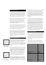
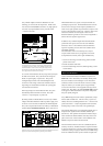
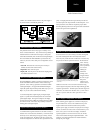
Carefully Selected Parts
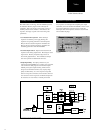
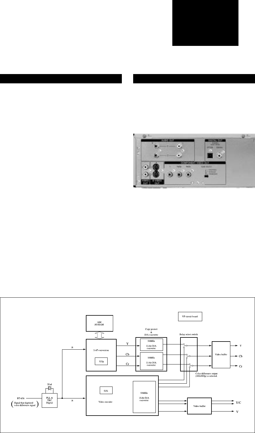
Fig. 14: Overview of the video processing circuit board.
DVD Technical Notes
Video