


– 53 –
KP-48V85/53V85/61V85
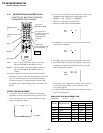
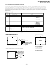
RM-Y905RM-Y905 RM-Y905
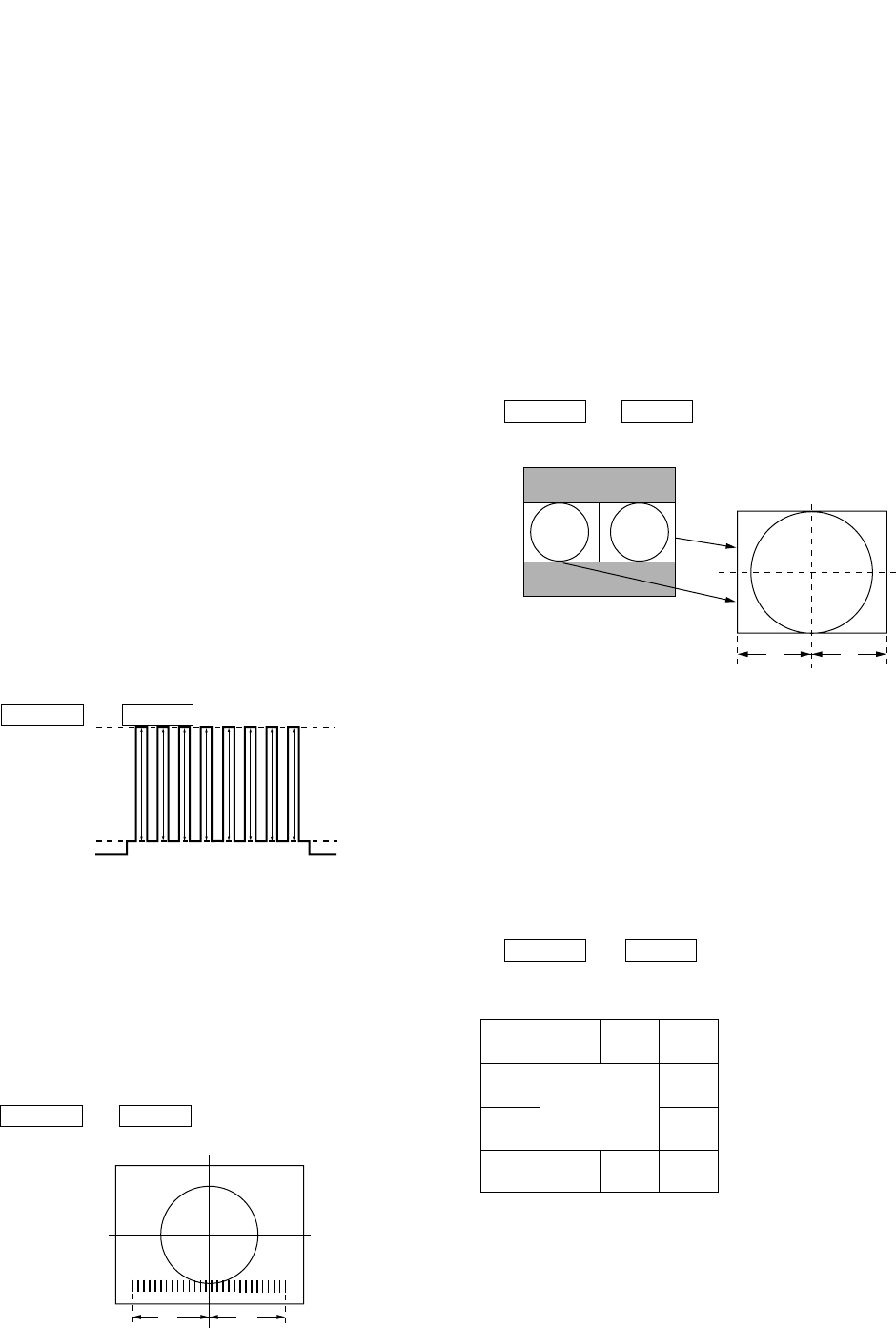
5-7. PIP ACQUISITION AREA ADJUSTMENT
(PP-MAHP, SAHP)
1. Set the SPLIT mode.
2. Receive the monoscope signal on the main/sub picture.
3. Check the monoscope position of each picture.
A=B
4. If necessary, set to service mode and adjust "PP-MAHP,
SAHP".
5. Write the data into memory.
MUTING n ENTER
Fig. 5-7
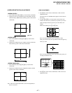
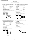
5-5. SUB-HUE , SUB-COLOR AND MAIN
CONTRAST ADJUSTMENT (MC-MYDR,
MSHU, MSCL, SC-SSHU, SSCL)
1. Receive the color-bar signal.
2. Mode : Personal 1 or 2.
PICTURE : maximum
COLOR : center
BRIGHTNESS : center
TRINITONE : medium
SERVICE DATA MC-MYDR : 22
SERVICE DATA MC-MSHU : 31
SERVICE DATA MC-MSCL : 31
SERVICE DATA SC-SSHU : 31
SERVICE DATA SC-SSCL : 31
3. Set to service mode and set to P & P model .
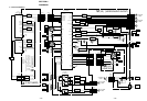
4. Connect an oscilloscope between pin 5 of CN204 (A board)
connecter and ground.
5. Select “ MC-MYDR”, and adjust them to have VB1 = VB5
in the waveform levels.
6. Select “ MC-MSCL, SC-SSCL” and adjust so that the wave
form shows VB1=VB4 and VB5=VB8.
7. Select “ MC-MSHU, SC-SSHU” and adjust so that the wave
form shows VB2=VB3 and VB6=VB7.
8. Write the data into memory.
MUTING n ENTER
VB1 VB2 VB3 VB4 VB5 VB6 VB7 VB8
Fig. 5-5
X1 = X2
X1
X2
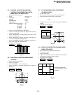
5-6. BAR DISPLAY POSITION ADJUSTMENT
(OP-DISP)
1. Receive the monoscope signal.
2. Set to service mode.
3. Push “ PICTURE +” . (Bar is displayed)
4. Select “ OP-DISP ” , and adjust so that the bar is as shown in
the figure.
5. Write the data into memory.
MUTING n ENTER
Fig. 5-6
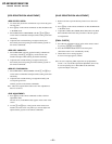
5-8. DISPLAY POSITION FOR CHANNEL INDEX
MODE (CCD-CCHP)
1. Recive the broadcast signal for main picture.
2. Set to service mode.
3. Select index mode.
4. Adjust “ CCD-CCHP” to get all channel number displays
into picture area without being on border.
5. Write the data into memory.
MUTING n ENTER
Fig. 5-8
AB
2X 5X
5
7X 9X
KEEP ONE CHARACTER
SPACE BETWEEN CH# AND
BORDER.
125X
11X
36X
13X
23X 19X 17X
14X