


10
CONTROL SCONTROL S
DOLBY DIGITAL
OUT
(OPTICALL)
IN
OUT
SD/HD
S VIDEO
S-LINK/
CONTROL S
OUT
S-LINK/
CONTROL S
IN
VIDEO
AUDIO
L
R
R
VIDEO
L
AUDIO
VHF/UHF
AUX
(MONO)
IN OUT
VIDEO 1 VIDEO 3 VIDEO 4 (DVD) SELECT
Y
P
B
PR
LINE
OUT
OUT
IN
AUDIO R AUDIO L VIDEO
S VIDEO
VHF/UHF
LINE
IN
OUT
IN
VHF/UHF
(DTV)
S VIDEO
VIDEO
VIDEO OUT
3
Y
P
B
PR
R
G
B
HD
VD
AUDIO OUT
L
(MONO)
R
1
2
4
1
2
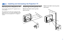
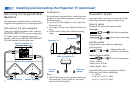
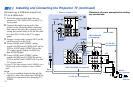
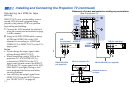
Installing and Connecting the Projection TV (continued)
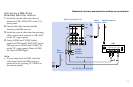
Connecting a VCR and projection
TV to a cable box
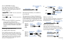
1 Attach the coaxial cable from the roof
antenna to VHF/UHF (DTV) on the TV’s
lower panel.
2 Connect the single (input) jack of the
splitter to the incoming cable connection,
and connect the other two (output) jacks
(using the coaxial cable) to IN on the cable
box and VHF/UHF on the TV’s upper
panel.
3 Using a coaxial cable, connect OUT on the
cable box to IN on the VCR.
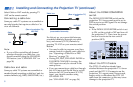
4 Using AUDIO and S VIDEO* cables,
connect AUDIO and S VIDEO OUT on the
VCR to AUDIO and S VIDEO IN on the
TV’s upper panel (White-AUDIO Left,
Red-AUDIO Right).
5 Using AUDIO and S VIDEO* cables,
connect AUDIO and S VIDEO IN on the
VCR to AUDIO and S VIDEO OUT on the
TV’s lower panel.
* If your VCR is not equipped with S VIDEO, use a
VIDEO cable (yellow) instead of the S VIDEO
cable.
Note:
• To view scrambled channels through the
cable box, select the video input which the
cable box is connected to by pressing TV/
VIDEO.
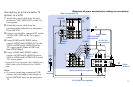
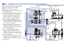
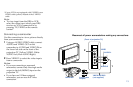
Coaxial cable
AUDIO-R
Cable/
Antenna
VCR
1
2
YC-15V/30V (not supplied)
4
3
Cable box
Splitter
(not supplied)
YC-15V/30V
(not supplied)
Roof
antenna
2
S VIDEO
AUDIO-L
S VIDEO
AUDIO-L
AUDIO-R
(Rear of projection TV)
5
VIDEO
VIDEO
VMC-810S/820S (not supplied)
VMC-810S/820S
(not supplied)
Disconnect all power sources before making
any connections.