


6
Names and Functions of Parts
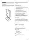
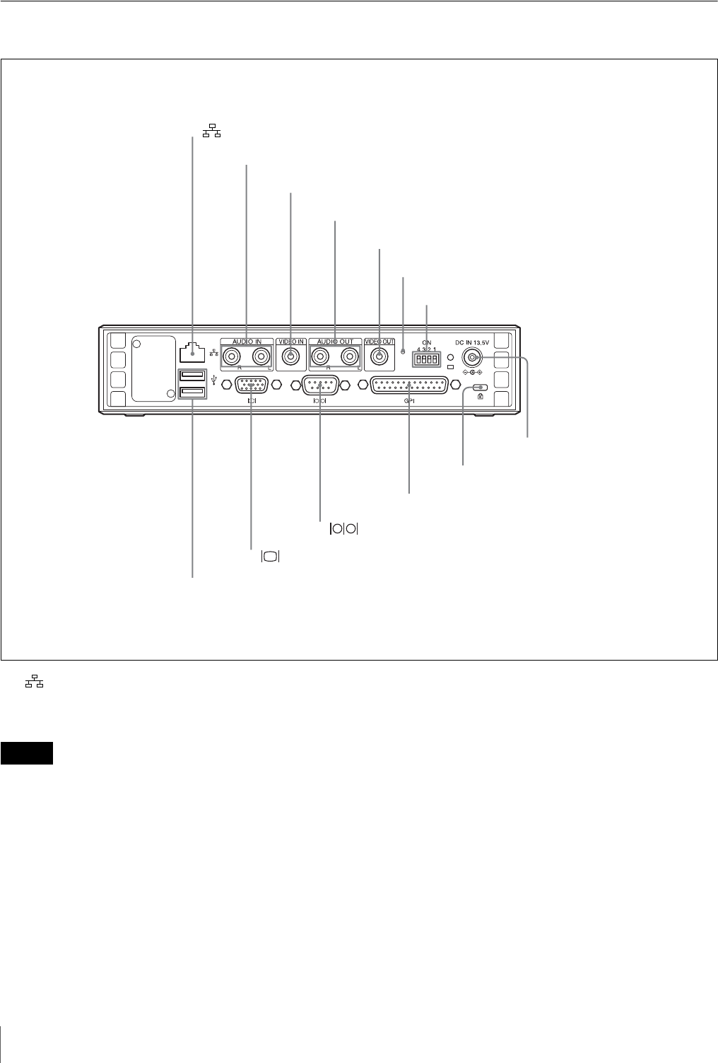
Rear Panel
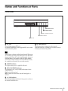
a (network) connector (RJ-45 modular jack)
This is a 10BASE-T/100BASE-TX connector for network
(Ethernet) connection.
When using a LAN cable: For safety, do not connect the
unit to a connector for peripheral device wiring that might
have excessive voltage.
b AUDIO IN L/R connectors (pin jacks)
These input analog audio signals.
c VIDEO IN connector (pin jack)
This inputs the analog composite video signal.
d AUDIO OUT L/R connectors (pin jacks)
These output the playback audio as an analog signal. For a
stereo signal, connector L outputs the left channel, and
connector R outputs the right channel
e VIDEO OUT connector (pin jack)
This outputs the playback video as a composite signal.
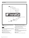
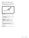
f Reset button
Used to forcibly restart this unit when it hangs or freezes.
Push this button using a sharply pointed tools, such as a
pencil or stretched paper clip.
g Dip switches
Used for various services. Set all switches to OFF.
1 (Network) connector
5 VIDEO OUT connector
2 AUDIO IN L/R connectors
4 AUDIO OUT L/R connectors
0 GPI connector
6 Reset button
9 Cable lock
7 Dip switches
qa (SERIAL) connector
qs (Analog RGB OUT) connector
qd USB connectors
8 DC IN 13.5V connector/Metal cable
retainer
3 VIDEO IN connector
Caution