


Just like the PFL switches on the channels, you can monitor the AUX 1-4 outputs by pressing the latching AFL
switch. This routes the AUX output signal to the MONITOR or PHONES, replacing any existing signal (normally
the Monitor receives either MIX or the Tape Return, depending on the position of the MIX switch - see below). The
RIGHT PPM METER also switches from the selected source to display the PFL/AFL signal and the PFL/AFL LED
lights to warn that a PFL or AFL switch is pressed. When you let go of the switch the Monitor returns to the previous
source.
MASTER SECTION - STEREO RETURNS
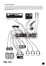
Two Stereo Return sections each comprise a pair of similar inputs suitable for -10dBV and +4dBu sources. The
inputs are unbalanced, and separate jacks are provided for the Left and Right source signals. A mono signal may
be plugged into the Left socket only for each pair to be fed equally to left and right busses.
Each section is provided with a routing switch to select between a pair of Groups (switch released) or MIX (switch
pressed). Stereo Returns A & B feed Groups 1 and 2, while Returns C & D feed Groups 3-4. PFL listening is
provided from a combination of all Stereo Returns through the STEREO RTNS PFL switch on the monitor section
(see below).
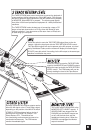
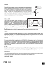
MASTER SECTION - GROUPS
Four group outputs are available, arranged as pairs, which may be fed from the
Channels or the Stereo Returns. Each Group output is ground
compensated/impedance balanced and is provided with a pre-fade insert point.
The MIX switch routes the Groups as a stereo pair to Mix Left/Right, Groups 1
and 3 feeding Mix Left and Groups 2 and 4 feeding Mix Right. Each pair of
Groups may feed post-fade to two Aux busses as a stereo pair, with a choice of
Aux 5/6 or 7/8 depending on the position of the 7-8 switch. These controls will
be found particularly useful for sending to reverb units, side fill feeds, alternate
PA stacks or individual zones in clubs.
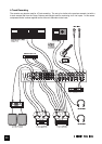
MIX OUTPUT
The stereo MIX FADER sets the final level of the ground compensated MIX
outputs. This should normally be set close to the ‘0’ mark if the input GAIN
settings have been correctly set, to give maximum travel on the fader for
smoothest control. If, even with correct input settings, you find that you are working with the mix fader very low,
then turn your power amplifiers down so that you can bring the fader level back to normal.
The BAL control trims the relative levels of Left and Right Mix signals and this is positioned
before
the Insert point
so that the Mix signal can be balanced before any compressor or other external processing unit. Note that the Mix
signal is always displayed on the VU Bargraph Meter above the fader (see below).
Tape SendS
The pre-fade mix signal is provided on independent Tape Send jacks, which are an ideal source for recording a
performance and are suitable for a -10dBV tape input.
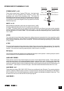
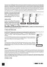
BARGRAPH METERS
Two types of Bargarph Meter are provided, to suit individual preferences and signal types, which provide visible
control of the signal at selected points in the mixer.
The three-colour VU Bargarphs display the MIX signal at all times, and sample the signal after the Balance control
and Insert point. The ‘0’ mark on the meter corresponds to a nominal +4dBu sine wave output.
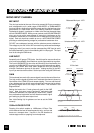
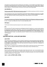
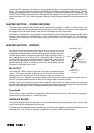
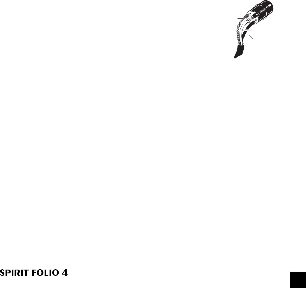
1. Screen
3. Ground
Sense(-ve)
2. Hot(signal)
Ground
Compensated
Output
Mix Output - XLR
18