


5-12
SUPERSERVER 6012P-6 User’s Manual
5-8 Connector Definitions
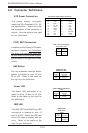
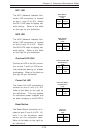
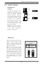
Power LED
The Power LED connection is lo-
cated on pins 15 and 16 of JF2.
Refer to the table on the right for
pin definitions.
Pin
Number
15
16
Definition
Vcc
Control
PWR_LED Pin Definitions
(JF2)
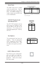
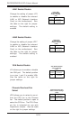
HDD LED
The HDD (IDE Hard Disk Drive) LED
connection is located on pins 13
and 14 of JF2. Attach the IDE hard
drive LED cable to display disk ac-
tivity. Refer to the table on the
right for pin definitions.
HDD LED Pin
Definitions
(JF2)
Pin
Number
13
14
Definition
Vcc
HD Active
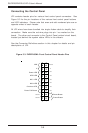
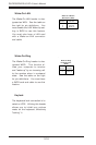
ATX Power Connection
The power supply connector
meets the SSI (Superset ATX) 20-
pin specification. Make sure that
the orientation of the connector is
correct. See the table on the right
for pin definitions.
Pins
1 thru 4
5 thru 8
Definition
Ground
+12v
8-Pin +12v Power Supply
Connector (J15)
ATX Power Supply 20-pin Connector
Pin Number Definition
11 +3.3V
12 -12V
13 COM
14 PS_ON
15 COM
16 COM
17 COM
18 -5V
19 +5V
20 +5V
Pin Number Definition
1 +3.3V
2 +3.3V
3 COM
4 +5V
5 COM
6 +5V
7 COM
8 PW-OK
9 5VSB
10 +12V
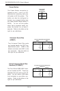
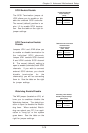
NMI Button
The non-maskable interrupt button
header is located on pins 19 and
20 of JF2. Refer to the table on
the right for pin definitions.
Pin
Number
19
20
Definition
Ground
Control
NMI Button Pin
Definitions (JF2)
PWR_SEC Connection
In addition to the Primary ATX power
connector (above), the Secondary
12v 8-pin J15 connector must also
be connected to your power supply.
See the table on the right for pin defi-
nitions.