


P6701B and P6703B Performance Verification
8
P6701B, P6703B, and P6723 Service Manual
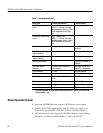
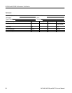
Table 7: Test equipment (cont.)
Description Example productMinimum requirements
P6703B only: 1310 nm cal
source
output > 200uW
1
,
stability > 0.1 dB over 5 minutes,
modulated square wave @ 10 kHz
with off m odulati on at zero-light
level
P6703B only: 1550 nm cal
source
output > 200uW (CW)
1
,
stability > 0.1 dB over 5 minutes,
modulated square wave @ 10 kHz
with off m odulati on at zero-light
level
RF power meter noise<.1mV,BW>4GHz HP 437B with power sensor
HP 8481D
P6703B only: 1300 nm
impulse generator
OIG 502
P6701B only: 850 nm
impulse generator
OIG 501
Sampling oscilloscope 11K (1140X, CSA40xX, or
DSA60X)
Adjustable optical
attenuator
4 decades, 50um core fiber, FC-
style connectors
JDS 5000L with 62 m
fiber with FC connectors
Digital voltm eter 4 1/2 digit Tektronix DMM916
50 ohm termination ± 1% 011-0049-01
Optical cable FC-FC multimode, 62. 5um, 2
meters
174-2322-00
Inline opt ical adapter FC female to FC female 131-5039-00
TekProbe Power Supply Tektronix 1103
Low-pass filter 1GHz Mini Ci rcuits SLP 1000
1
CW and modulated mode available: modulation wi th OFF level at or below 0.1uW,
optical falltime < 1us
Noise Equivalent Power
1. Power the P670XB under test using an 1103 Tekprobe power supply.
2. Connect the P670XB output channel from the 1103 power supply to the
power meter input with the 1 GHz filter in series with this connection.
3. With the dust cover on the input to the P670XB, the power meter reading
should be ≤ 15 nW for the P6701B and ≤ 7 nW for the P6703B.