


www.ti.com
Optional Configuration
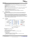
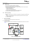
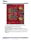
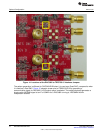
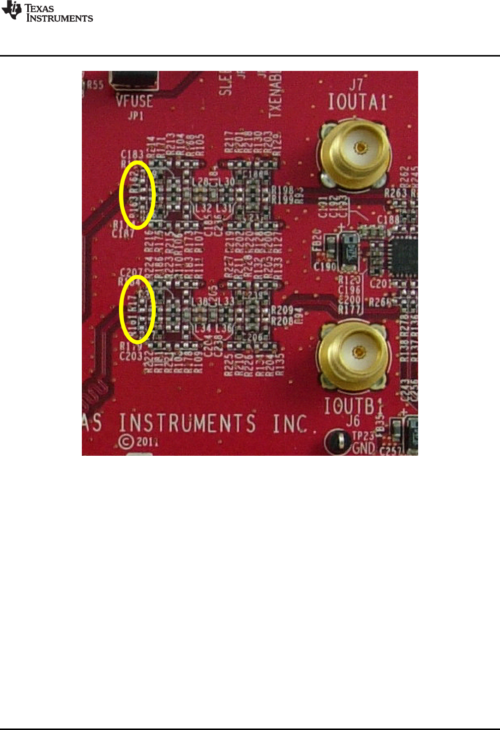
Figure 11. Locations of DAC348x to Transformer Output Jumper Locations
• Provide the clock input 1228.8 MHz at 1.5Vrms at J9 SMA connector of the DAC3484 EVM
• Turn on power to the board and press the reset button on the EVM
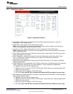
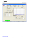
• Press the “Reset USB Port” button in GUI and verify USB communication.
• Switch to the INPUT tab of GUI
• Click “LOAD REGS”, browse to the installation folder and load example file
DAC3484_FDAC_1228p8MHz_4xint_NCO_30MHz_QMCon.txt. This file contains settings for 4x
interpolation with the DAC3484 running at 1228.8MSPS. Load this file and wait a couple of seconds for
the settings to go into effect.
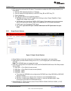
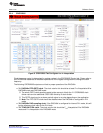
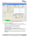
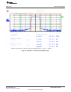
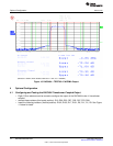
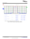
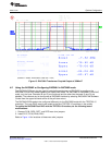
• Verify the spectrum using the Spectrum Analyzer at the four DAC outputs of the DAC EVM (J7, J6, J3,
and J2).
• (Toggle the SIF SYNC button to sync the appropriate digital blocks, if example file with NCO
setting is used)
13
SLAU336–March 2011 DAC3484/DAC3482 EVM
Submit Documentation Feedback
© 2011, Texas Instruments Incorporated